Pneumatic System
141
Introducing the Packer Air System
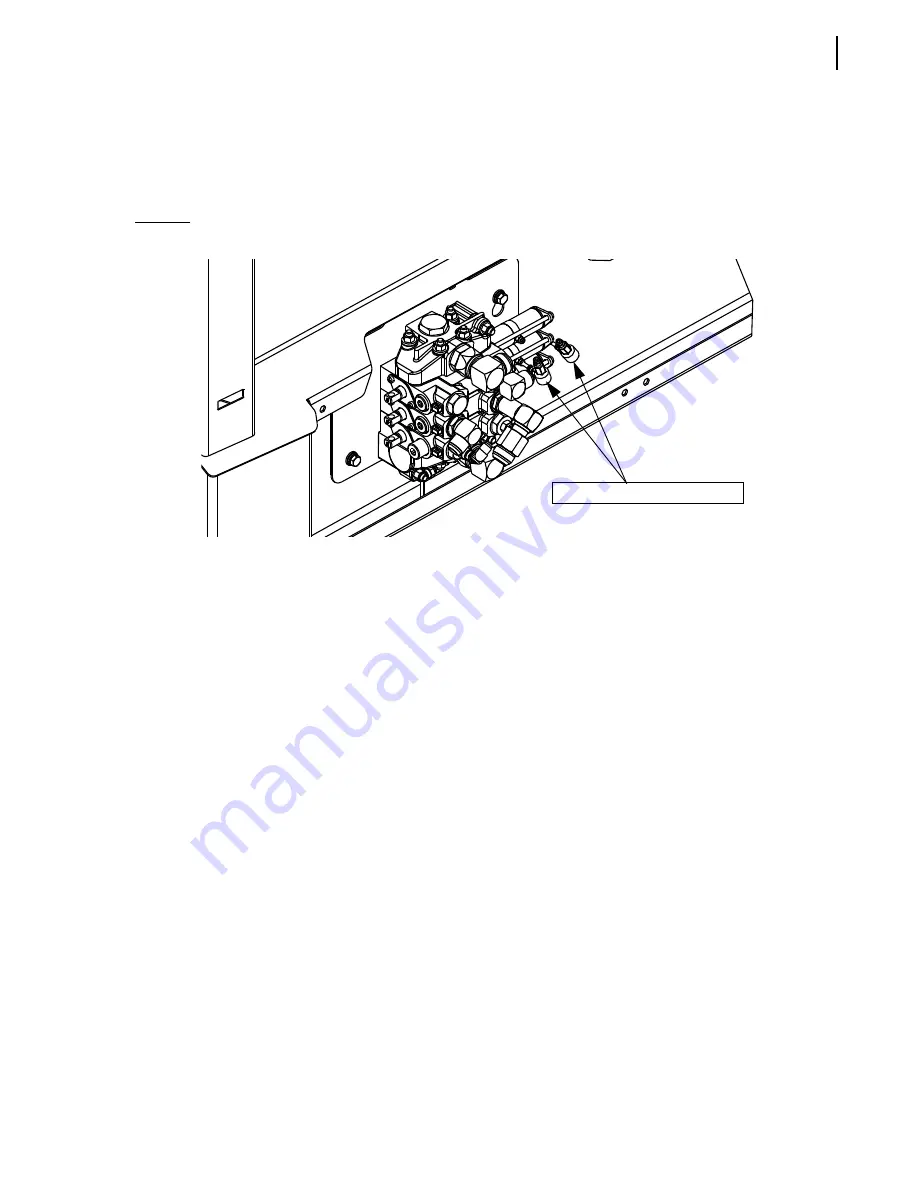
The hydraulic valve, which controls some of the hydraulic functions, is equipped with air actuators.
The packer air actuator pushes back and forth on the hydraulic spool inside the valve, resulting in a
movement of the packer (extension or retraction).
Figure 7-6 Packer air actuator
As the packer reaches the end of a stroke, the proximity switch, located behind the packer, sends a
signal to the electronic module to indicate that the packer has reached the end of its stroke. The
packer module then operates the air solenoid valve inside the air control box with a 12volt signal
(one signal for packer extend, one signal for packer retract).
When receiving the 12-volt signal (extend or retract) from the module, the air solenoid valve enables
the air pressure to reach the actuator on the main control valve. The spool moves according to the
signal received.
Two quick exhaust valves, located close to the body main valve (see Figure 7-6), are designed to
release air pressure from lines going to the packer air actuator installed on the main control valve.
They release air when the packer reaches the end of a stroke, allowing the spool to move in the
opposite direction and prevent working against pressurized lines.
Quick exhaust valves
Summary of Contents for Automizer Versa Hand
Page 1: ...AUTOMIZER VERSA HANDTM MAINTENANCE MANUAL...
Page 2: ......
Page 3: ...AUTOMIZER VERSA HAND MAINTENANCE MANUAL...
Page 26: ...18 Safety...
Page 89: ...Lubrication 81 Figure 4 11 Lubrication chart Automizer...
Page 90: ...82 Lubrication Figure 4 12 Lubrication chart Versa Hand arm...
Page 94: ...86 Lubrication Figure 4 18 Cylinder retaining ring Cylinder retaining ring...
Page 95: ...Lubrication 87 Packer Lubrication Points...
Page 96: ...88 Lubrication Hopper Door Hopper door latch Hopper door hinges...
Page 105: ...Hydraulic System 97...
Page 127: ...Hydraulic System 119 Figure 5 29 Detecting cylinder internal leaks 1 2 3 4 5 A A A...
Page 128: ...120 Hydraulic System Main Hydraulic Schematic...
Page 129: ...Hydraulic System 121 Hydraulic Schematic 96 Gallon Gripper...
Page 130: ...122 Hydraulic System Hydraulic Schematic 300 Gallon Gripper...
Page 131: ...Hydraulic System 123...
Page 132: ...124 Hydraulic System...
Page 137: ...Electrical System 129 Electrical Schematics Console 1...
Page 138: ...130 Electrical System Console 2...
Page 139: ...Electrical System 131 Arm Control...
Page 140: ...132 Electrical System Chassis...
Page 141: ...Electrical System 133 Main Body...
Page 142: ...134 Electrical System Hopper...
Page 143: ...Electrical System 135 Arm...
Page 144: ...136 Electrical System...
Page 151: ...Pneumatic System 143 Pneumatic System Schematic...
Page 152: ...144 Pneumatic System...
Page 155: ...Troubleshooting 147 Figure 8 4 Ball end hex wrench metric and SAE...
Page 164: ...156 Troubleshooting Figure 8 9 Tailgate locking mechanism...
Page 166: ...158 Troubleshooting...
Page 189: ...Lifting Arm 181...


