106
C
HAPTER
3
Maintenance
9.
Raise the crusher panel until it
reaches the end of its stroke.
Hold the lever in order to make
the pressure build up in the
system;
10.
Check the pressure at the same
time on the pressure gauge;
11.
Adjust the main relief as needed
(Figure 168. “Main valve”) by
loosening the lock nut and
turning the adjustment screw
clockwise to increase the
pressure or the other way to
reduce it;
Figure 168. Main valve
12.
When finished, hold the
adjustment screw and tighten
the lock nut.
Crusher Panel
Control Lever
Lock Nut
Main Relief Valve
Adjustment
Pressure Adjustment Table
Pump
Chassis
Cylinder
Bore
(Packer)
Main Relief
Pressure
(±50 PSI)
Dump Valve
Pressure
(±50 PSI)
V
ANE
P
UMP
6
X
4
4”
3000 PSI@
1200 RPM
3300 PSI@
1200 RPM
2
X
4
4”
3000 PSI@
1200 RPM
3300 PSI@
1200 RPM
Summary of Contents for expert 2000
Page 1: ......
Page 2: ......
Page 3: ...MAINTENANCE MANUAL 12 14 2006 Part 55379 ...
Page 4: ......
Page 10: ...viii Table of Contents ...
Page 96: ...86 CHAPTER 3 Maintenance Figure 141 Proximity switch front view ...
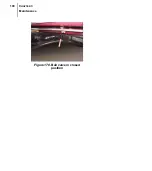
Page 118: ...108 CHAPTER 3 Maintenance Figure 170 Ball valve in closed position ...
Page 140: ...130 CHAPTER 4 Lubrication PACKER ...
Page 141: ...131 Expert t 2000TM Maintenance Manual BODY CHASSIS HINGES ...
Page 142: ...132 CHAPTER 4 Lubrication HOPPER SECTION STANDARD VERSION ...
Page 143: ...133 Expert t 2000TM Maintenance Manual CRUSHER PANEL ...
Page 144: ...134 CHAPTER 4 Lubrication FULL WIDTH TAILGATE ...
Page 154: ...144 CHAPTER 5 Troubleshooting ...
Page 156: ...146 Appendix CONNECTORS Commonly used Electrical Connectors Deutsch AMP ...
Page 168: ...158 Appendix ...
Page 170: ...160 Appendix ...
Page 171: ......
Page 172: ......


