51
Expert(t) 2000
TM
Maintenance Manual
6.
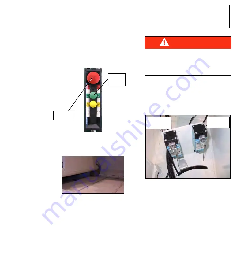
Push the green
S
TART
C
YCLE
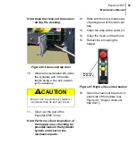
button to fully extend the packer,
then push the red emergency
S
TOP
button when the packer is
fully extended.
Figure 71. Right-hand side control
station
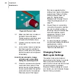
Figure 72. Extended packer
7.
Apply the
Lockout/Tagout
procedure. Refer to “Lockout/
Tagout Procedure” on page 8.
8.
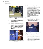
Locate the limit switches at the
front end of the body, on its
right-hand side, between the cab
and the body (Figure 73. “Packer
cylinder limit switches”);
Figure 73. Packer cylinder limit
switches
9.
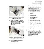
Srew or unscrew the
limit-switch-finger adjustment
screw (Figure 74. “Packer
cylinder finger”) so the cylinder
lever can trigger the switch when
the packer cylinder reaches this
position;
Emergency
Stop Button
Start
Cycle
Button
DANGER
A
PPLY
THE
LOCKOUT
/
TAGOUT
PROCEDURE
TO
PREVENT
ANY
ENGINE
START
-
UP
.
Packer-
Retraction
Limit Switch
Packer-
Extension
Limit Switch
Summary of Contents for expert 2000
Page 1: ......
Page 2: ......
Page 3: ...MAINTENANCE MANUAL 12 14 2006 Part 55379 ...
Page 4: ......
Page 10: ...viii Table of Contents ...
Page 96: ...86 CHAPTER 3 Maintenance Figure 141 Proximity switch front view ...
Page 118: ...108 CHAPTER 3 Maintenance Figure 170 Ball valve in closed position ...
Page 140: ...130 CHAPTER 4 Lubrication PACKER ...
Page 141: ...131 Expert t 2000TM Maintenance Manual BODY CHASSIS HINGES ...
Page 142: ...132 CHAPTER 4 Lubrication HOPPER SECTION STANDARD VERSION ...
Page 143: ...133 Expert t 2000TM Maintenance Manual CRUSHER PANEL ...
Page 144: ...134 CHAPTER 4 Lubrication FULL WIDTH TAILGATE ...
Page 154: ...144 CHAPTER 5 Troubleshooting ...
Page 156: ...146 Appendix CONNECTORS Commonly used Electrical Connectors Deutsch AMP ...
Page 168: ...158 Appendix ...
Page 170: ...160 Appendix ...
Page 171: ......
Page 172: ......


