Hydraulic System
269
4.
Loosen the breather cap on the hydraulic tank to depressurize the tank.
If tank is of the pressurized type.
5.
Disconnect the electric coil on the dump valve, if equipped.
6.
Place a pan under the pump to catch dripping oil and unscrew all hydraulic hoses (4) that are
attached to the pump.
7.
Remove the dump valve.
N
OTE
:
The dump valve is usually, but not necessarily, located atop the pump.
N
OTE
:
Always reinstall the dump valve and its components (shims, block assembly) as they were
before uninstallation. Make sure you do not invert them.
8.
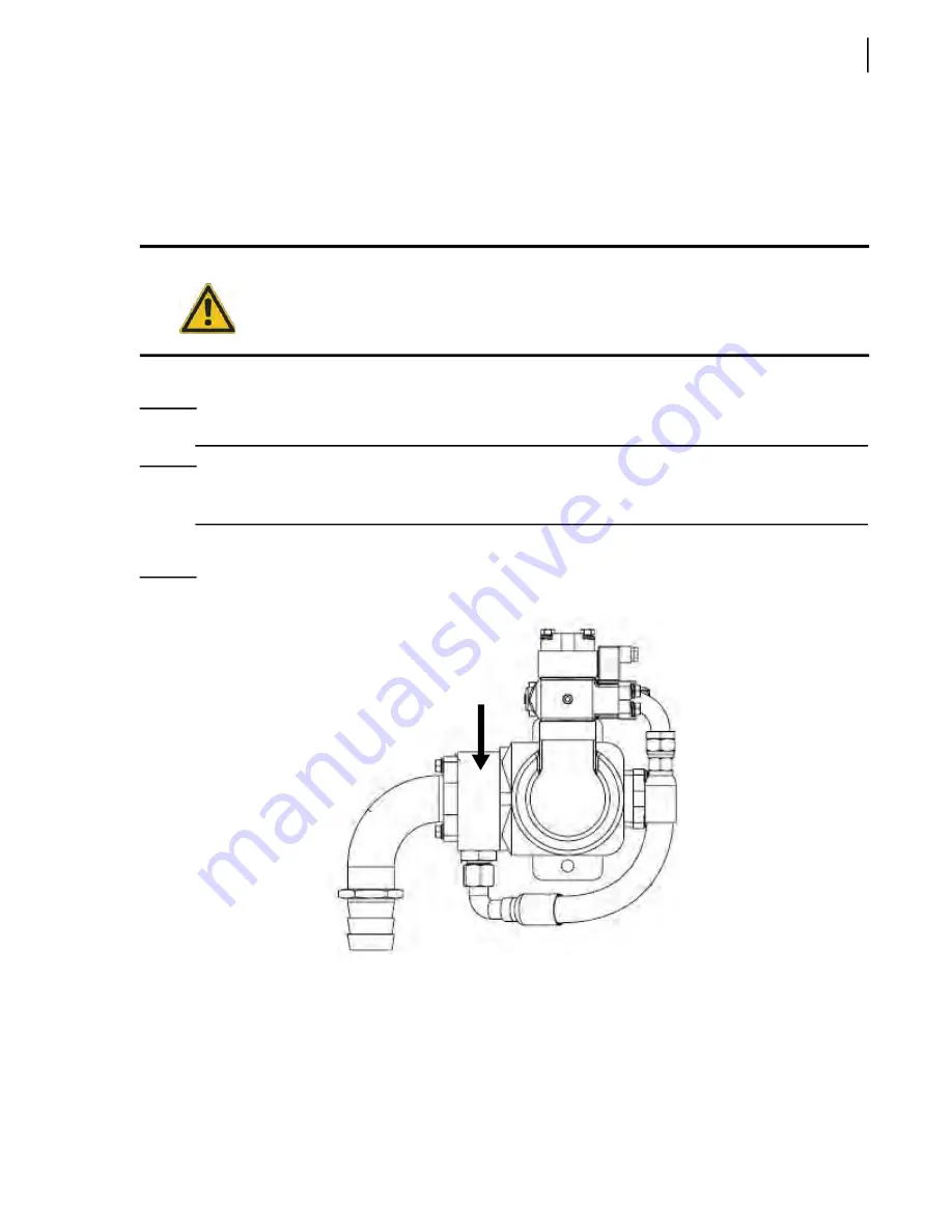
Remove the suction block (see Figure 5
10) and save it for the new pump.
Figure 5
-
10 Suction block
9.
Disconnect the drive shaft by removing the 4 bolts that secure the shaft to the PTO.
Some mechanics may rather want to disconnect the drive shaft from the pump.
The choice is up to the mechanics and is based on the type of chassis the vehicle is built on.
10.
Attach the pump to a lifting device and remove both 5/8” bolts that hold the pump to the pump
support.
11.
Remove the pump.
Caution!
Before disconnecting hydraulic hoses from the pump, place a pan under it to catch oil that
may drip down from disconnected lines.
Summary of Contents for EXPERT
Page 1: ...EXPERT TM MAINTENANCE MANUAL...
Page 2: ......
Page 3: ...EXPERT MAINTENANCE MANUAL...
Page 10: ...viii Table of Contents...
Page 18: ...8 Introduction...
Page 244: ...234 General Maintenance...
Page 251: ...Lubrication 241 Figure 4 11 Glass compartment lubrication chart optional...
Page 252: ...242 Lubrication Figure 4 12 EXPERT lubrication chart...
Page 264: ...254 Lubrication...
Page 320: ...310 Hydraulic System...
Page 357: ...Troubleshooting 349...
Page 358: ...350 Troubleshooting...
Page 386: ...378 Multiplexing...


