Pneumatic System
325
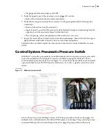
Connect a multimeter set to the red and black wires of the air pressure switch and select “Continuity”
on the multimeter. Using the 3/32” Allen key, adjust the needle in until the multimeter shows
continuity between the red and black wires. Remove the multimeter and air pressure regulator, then
connect the air pressure switch wires and re-assemble the pneumatic valve box.
N
OTE
:
If your E
XPERT
™ unit is equipped with an electro-hydraulic valve — hence no pneumatic valve
box on the truck — the signal of this pressure switch is bypassed.
Air Tanks
To drain the air tanks
, apply the following procedure:
1.
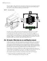
Locate the drain valves on the air tanks (see Figure 7
6).
N
OTE
:
Some trucks are equipped with more than one drain valve.
2.
Open the valves by turning them one-quarter turn clockwise.
I
MPORTANT
:
Before opening the valves, be sure to stay away from the stream.
3.
Leave the valves open until moisture is removed.
4.
When all moisture has been drawn out, close the valves by turning them one-quarter turn
counter-clockwise.
Figure 7
-
6 Drain valves
Caution
The operator
must
wear safety glasses to protect his eyes against dust and suspended
matters. The operator must also stay away from the stream to avoid potential injuries.
Summary of Contents for EXPERT
Page 1: ...EXPERT TM MAINTENANCE MANUAL...
Page 2: ......
Page 3: ...EXPERT MAINTENANCE MANUAL...
Page 10: ...viii Table of Contents...
Page 18: ...8 Introduction...
Page 244: ...234 General Maintenance...
Page 251: ...Lubrication 241 Figure 4 11 Glass compartment lubrication chart optional...
Page 252: ...242 Lubrication Figure 4 12 EXPERT lubrication chart...
Page 264: ...254 Lubrication...
Page 320: ...310 Hydraulic System...
Page 357: ...Troubleshooting 349...
Page 358: ...350 Troubleshooting...
Page 386: ...378 Multiplexing...


