388
Lifting Arms
Each of the automated arms has its own arm valve to which a holding valve is attached.
4.
Connect a pressure gauge to the quick coupler (see Figure 10
11) of the arm valve that controls
the right arm or the left arm.
Proceed with one arm at the time.
5.
Slowly move the lever on the arm in/out section of the arm valve (see Figure 10
5) and read the
pressure on the pressure gauge at the time the arm starts extending.
The extending movement must begin when the pressure reaches 650 PSI.
6.
If the pressure is below or over that value when the arm starts extending, adjust the holding valve
pressure accordingly using the adjustable cartridge (see Figure 10
12).
N
OTE
:
Turn the screw counter-clockwise to increase pressure or clockwise to reduce pressure.
7.
Repeat same procedure for the other arm.
Gripper Auto-Closing System
The H
ELPING
-H
AND
™
automated arm is equipped with a safety system that closes the gripper
automatically when the arm is returning to the hopper. The auto-closing system prevents the gripper
from hitting the hopper walls, thus avoiding potential damage to the gripper.
If the operator raises the arm without closing the gripper, the auto-closing system will automatically
close the gripper when it reaches a preset height.
N
OTE
:
If the vehicle is parked for a long period of time with the gripper inside the hopper, the gripper
cylinder may leak pressure, causing the gripper to open by itself. But as soon as the hydraulic
system is brought online (P
UMP
switch “ON”), the auto-closing system closes the gripper
automatically before the operator can move the arm. In this, the system acts as though the
operator had pushed the
CLOSE
GRIPPER
button on the joystick.
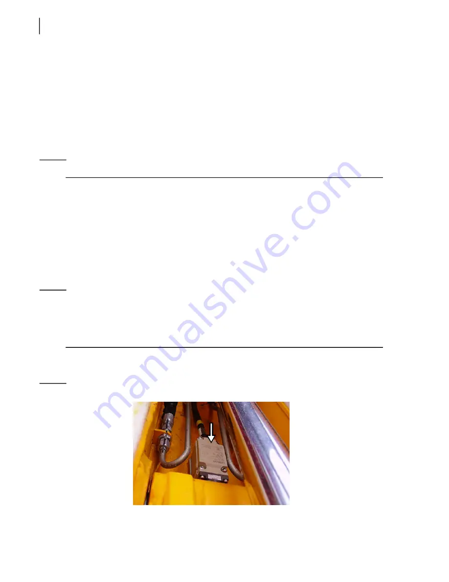
The auto-closing system is controlled by a non-adjustable limit switch located inside the arm slide
13).
Figure 10
-
13 Gripper Auto-Closing limit switch
Summary of Contents for EXPERT
Page 1: ...EXPERT TM MAINTENANCE MANUAL...
Page 2: ......
Page 3: ...EXPERT MAINTENANCE MANUAL...
Page 10: ...viii Table of Contents...
Page 18: ...8 Introduction...
Page 244: ...234 General Maintenance...
Page 251: ...Lubrication 241 Figure 4 11 Glass compartment lubrication chart optional...
Page 252: ...242 Lubrication Figure 4 12 EXPERT lubrication chart...
Page 264: ...254 Lubrication...
Page 320: ...310 Hydraulic System...
Page 357: ...Troubleshooting 349...
Page 358: ...350 Troubleshooting...
Page 386: ...378 Multiplexing...


