124
Troubleshooting
Pump
The pump is operated by a control rocker switch located on the control panel. When the pump is
engaged, the switch turns to green.
Three conditions must be met for the pump to engage and for the rocker switch to turn green:
Engine speed must be lower than 900
rpm
Emergency S
TOP
button (red) pulled out
Engine speed is verified by the transmission ECU.
If the pump does not engage when the pump rocker switch is turned on, it may be related to a voltage
supply problem in the pump circuitry.
There is a pump test that can help resolve pump-related problems. For more information on that or
for advanced troubleshooting, please call Labrie
Plus
.
Prior to conducting a pump test, ensure that all these conditions are met:
Parking brake is applied
Engine is running (at idle speed)
Transmission is in “Neutral”
Emergency S
TOP
button(s) is pulled out
Pump (
PTO
) switch is ON
N
OTE
:
Neither the engine throttle nor the transmission not being in Neutral will affect pump
operation once the pump is engaged.
Pump Cavitation
Cavitation is defined as the formation of air pockets in a moving fluid. Air in the hydraulic oil causes
excessive wear and noise. Make sure to prime the pump properly after replacement or after flushing
the hydraulic system (refer to “Priming a New Pump” on page 80). When the pump is properly
primed, cavitation disappears after a short period of time because air is returning to the hydraulic
tank.
If the pump is still generating unusual noise after performing the pump priming procedure, then you
will have to bleed the hydraulic system.
To do so:
1.
Apply all safety measures to ensure safety around the vehicle at all times.
2.
Connect a 0–4000
psi gauge to the main valve to ensure that no pressure has built up in the
system.
3.
Apply the parking brake and start the engine.
4.
Engage the hydraulic pump (
PTO
switch “ON”).
5.
Place a pan or a bucket under the plug located on the output section of the main control valve and
slowly loosen the plug.
A mixture of oil and air will come out. Keep bleeding the oil until the pump noise stops.
Summary of Contents for MINIMAX
Page 1: ...MINIMAX TM MAINTENANCE MANUAL...
Page 2: ......
Page 3: ...MINIMAX MAINTENANCE MANUAL...
Page 8: ...vi Table of Contents Adjusting Arm Speed 164...
Page 30: ...22 Safety Figure 2 17 Drain valve on air tank...
Page 72: ...64 Lubrication Figure 4 10 Lubrication chart Helping Hand arm...
Page 80: ...72 Lubrication...
Page 90: ...82 Hydraulic System Figure 5 8 Oil temp level gauge Figure 5 9 Steel hydraulic tank...
Page 102: ...94 Hydraulic System Figure 5 21 Strainer assembly Strainer...
Page 106: ...98 Hydraulic System Figure 5 25 Detecting cylinder internal leaks 1 2 3 4 5 A A A...
Page 108: ...100 Hydraulic System...
Page 113: ...Electrical System 105 Electrical Schematics Cab Adaptation...
Page 114: ...106 Electrical System Cab Console Controls...
Page 115: ...Electrical System 107 Cab Controller...
Page 116: ...108 Electrical System Chassis...
Page 117: ...Electrical System 109 Body Module rear side...
Page 118: ...110 Electrical System Body Module front side...
Page 119: ...Electrical System 111 Tailgate Lighting...
Page 120: ...112 Electrical System Panic Bars Crusher Panel Tipper Interlocks...
Page 121: ...Electrical System 113 Cameras Switchpack Details Interlocks AUTO 10 SEC INHIBIT AUTO N AUTO ON...
Page 122: ...114 Electrical System...
Page 127: ...Troubleshooting 119 Figure 8 4 Ball end hex wrench metric and SAE...
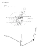
Page 134: ...126 Troubleshooting Figure 8 6 Tailgate locking mechanism...
Page 156: ...148 Multiplexing...
Page 162: ...154 Multiplexing...
Page 164: ...156 Lifting Arm Figure 10 1 Mounting bolts Figure 10 2 Helping Hand gripper Figure 10 3 Hoses...


