


Multiplexing
145
If you press a joystick button, the corresponding button on the display monitor will turn to green. If
nothing happens, there might be a communication problem between the joystick and the master
control module. Refer to maintenance personnel or Labrie
Plus
.
Also, if you move the joystick backwards, forwards or sideways, you should see the values under the
illustration changing. If no change occurs when moving the joystick, a communication problem
between the joystick and the master control module may be the cause. Refer to maintenance
personnel or Labrie
Plus
.
Press “Esc” to return to the preceding page.
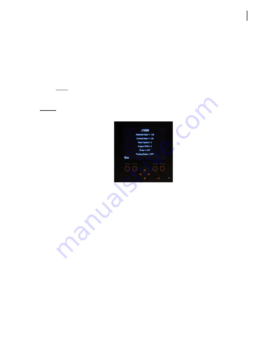
J1939
The J1939 page is useful when you need some specific information (e.g. current gear, road speed,
brake).
Figure 9-17 J1939 page
Your vehicle is equipped with 2
different CAN-based communication buses:
the
J1939 bus
, which is used for the chassis equipment; and
the
CANopen bus
, which is used for the body.
These 2
communication buses are completely independent of one another, except for some specific
data that are transferred from the chassis J1939 bus to Labrie’s multiplexed system in order to be used
by this system. These specific data are the following:
selected gear
current gear
road speed
engine RPM
brake
parking brake
Press “Esc” to return to the preceding page.
Module Software Version
In this section, you will find the software version currently used by each of the modules installed on
the truck and by the master control module.
Summary of Contents for MINIMAX
Page 1: ...MINIMAX TM MAINTENANCE MANUAL...
Page 2: ......
Page 3: ...MINIMAX MAINTENANCE MANUAL...
Page 8: ...vi Table of Contents Adjusting Arm Speed 164...
Page 30: ...22 Safety Figure 2 17 Drain valve on air tank...
Page 72: ...64 Lubrication Figure 4 10 Lubrication chart Helping Hand arm...
Page 80: ...72 Lubrication...
Page 90: ...82 Hydraulic System Figure 5 8 Oil temp level gauge Figure 5 9 Steel hydraulic tank...
Page 102: ...94 Hydraulic System Figure 5 21 Strainer assembly Strainer...
Page 106: ...98 Hydraulic System Figure 5 25 Detecting cylinder internal leaks 1 2 3 4 5 A A A...
Page 108: ...100 Hydraulic System...
Page 113: ...Electrical System 105 Electrical Schematics Cab Adaptation...
Page 114: ...106 Electrical System Cab Console Controls...
Page 115: ...Electrical System 107 Cab Controller...
Page 116: ...108 Electrical System Chassis...
Page 117: ...Electrical System 109 Body Module rear side...
Page 118: ...110 Electrical System Body Module front side...
Page 119: ...Electrical System 111 Tailgate Lighting...
Page 120: ...112 Electrical System Panic Bars Crusher Panel Tipper Interlocks...
Page 121: ...Electrical System 113 Cameras Switchpack Details Interlocks AUTO 10 SEC INHIBIT AUTO N AUTO ON...
Page 122: ...114 Electrical System...
Page 127: ...Troubleshooting 119 Figure 8 4 Ball end hex wrench metric and SAE...
Page 134: ...126 Troubleshooting Figure 8 6 Tailgate locking mechanism...
Page 156: ...148 Multiplexing...
Page 162: ...154 Multiplexing...
Page 164: ...156 Lifting Arm Figure 10 1 Mounting bolts Figure 10 2 Helping Hand gripper Figure 10 3 Hoses...


