


General Maintenance
43
When the Packer Retract
limit switch needs adjustment, it is usually because it no longer stops the
packer (bottoming out) or prevents automatic cycles from working properly. A well adjusted Packer
Retract limit switch should prevent the packer from making a knocking noise when it stops during
retraction in speed-up mode.
When this limit switch needs adjustment, the following procedure is recommended.
To adjust the Packer Retract limit switch:
1.
Set the parking brake.
2.
Start the engine and engage the hydraulic system (P
UMP
switch activated).
3.
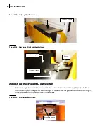
Press the yellow button to retract the packer to (+/-) 1/16” before the fully retracted position
(this is the measurement between the packer blade and the arm base wiper).
N
OTE
:
When in stowed position the packer blade must always make contact with the wiper.
4.
When the packer reaches the correct position, push the red emergency
STOP
5.
Disengage the hydraulic pump and turn off the engine.
6.
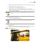
7.
Locate the Packer Retract limit switch lever (see Figure 3-24).
Figure 3-24 Packer retract limit switch lever
8.
Use an Allen key to loosen the locknut on the limit switch and determine the contact point where
the triggering should occur by moving the lever.
9.
Once you have determined the contact point where the triggering should occur, tighten back the
locknut.
Danger!
Never get on the hopper area while the engine is running.
Summary of Contents for MINIMAX
Page 1: ...MINIMAX TM MAINTENANCE MANUAL...
Page 2: ......
Page 3: ...MINIMAX MAINTENANCE MANUAL...
Page 8: ...vi Table of Contents Adjusting Arm Speed 164...
Page 30: ...22 Safety Figure 2 17 Drain valve on air tank...
Page 72: ...64 Lubrication Figure 4 10 Lubrication chart Helping Hand arm...
Page 80: ...72 Lubrication...
Page 90: ...82 Hydraulic System Figure 5 8 Oil temp level gauge Figure 5 9 Steel hydraulic tank...
Page 102: ...94 Hydraulic System Figure 5 21 Strainer assembly Strainer...
Page 106: ...98 Hydraulic System Figure 5 25 Detecting cylinder internal leaks 1 2 3 4 5 A A A...
Page 108: ...100 Hydraulic System...
Page 113: ...Electrical System 105 Electrical Schematics Cab Adaptation...
Page 114: ...106 Electrical System Cab Console Controls...
Page 115: ...Electrical System 107 Cab Controller...
Page 116: ...108 Electrical System Chassis...
Page 117: ...Electrical System 109 Body Module rear side...
Page 118: ...110 Electrical System Body Module front side...
Page 119: ...Electrical System 111 Tailgate Lighting...
Page 120: ...112 Electrical System Panic Bars Crusher Panel Tipper Interlocks...
Page 121: ...Electrical System 113 Cameras Switchpack Details Interlocks AUTO 10 SEC INHIBIT AUTO N AUTO ON...
Page 122: ...114 Electrical System...
Page 127: ...Troubleshooting 119 Figure 8 4 Ball end hex wrench metric and SAE...
Page 134: ...126 Troubleshooting Figure 8 6 Tailgate locking mechanism...
Page 156: ...148 Multiplexing...
Page 162: ...154 Multiplexing...
Page 164: ...156 Lifting Arm Figure 10 1 Mounting bolts Figure 10 2 Helping Hand gripper Figure 10 3 Hoses...


