


8
Troubleshooting
This chapter contains information to help you narrow
down and/or solve problems that might occur with
your M
INIMAX
™. Procedures throughout this chapter
require that the people performing troubleshooting
tasks have basic knowledge in electrical, hydraulic and
pneumatic systems.
The employer shall ensure that maintenance
personnel is properly trained prior to starting
troubleshooting.
Before performing maintenance on a vehicle, make
sure that all safety procedures are applied. The
lockout/tagout procedure outlined on page 20 is
mandatory.
commonly seen problems, or contact Labrie
Plus
to
talk to one of our product specialists.
I
MPORTANT
:
Schematics provided in this manual are for reference
only. Vehicle-specific schematics are provided in the
vehicle’s cab.
Tools
When trying to pinpoint the cause of a problem on a
vehicle, you need certain tools to test components of
electrical, hydraulic, and pneumatic systems. Below
you will find a list of the minimal tool set required to
perform troubleshooting procedures throughout this
manual. Brand names are only suggested.
Summary of Contents for MINIMAX
Page 1: ...MINIMAX TM MAINTENANCE MANUAL...
Page 2: ......
Page 3: ...MINIMAX MAINTENANCE MANUAL...
Page 8: ...vi Table of Contents Adjusting Arm Speed 164...
Page 30: ...22 Safety Figure 2 17 Drain valve on air tank...
Page 72: ...64 Lubrication Figure 4 10 Lubrication chart Helping Hand arm...
Page 80: ...72 Lubrication...
Page 90: ...82 Hydraulic System Figure 5 8 Oil temp level gauge Figure 5 9 Steel hydraulic tank...
Page 102: ...94 Hydraulic System Figure 5 21 Strainer assembly Strainer...
Page 106: ...98 Hydraulic System Figure 5 25 Detecting cylinder internal leaks 1 2 3 4 5 A A A...
Page 108: ...100 Hydraulic System...
Page 113: ...Electrical System 105 Electrical Schematics Cab Adaptation...
Page 114: ...106 Electrical System Cab Console Controls...
Page 115: ...Electrical System 107 Cab Controller...
Page 116: ...108 Electrical System Chassis...
Page 117: ...Electrical System 109 Body Module rear side...
Page 118: ...110 Electrical System Body Module front side...
Page 119: ...Electrical System 111 Tailgate Lighting...
Page 120: ...112 Electrical System Panic Bars Crusher Panel Tipper Interlocks...
Page 121: ...Electrical System 113 Cameras Switchpack Details Interlocks AUTO 10 SEC INHIBIT AUTO N AUTO ON...
Page 122: ...114 Electrical System...
Page 127: ...Troubleshooting 119 Figure 8 4 Ball end hex wrench metric and SAE...
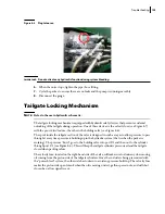
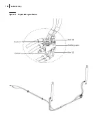
Page 134: ...126 Troubleshooting Figure 8 6 Tailgate locking mechanism...
Page 156: ...148 Multiplexing...
Page 162: ...154 Multiplexing...
Page 164: ...156 Lifting Arm Figure 10 1 Mounting bolts Figure 10 2 Helping Hand gripper Figure 10 3 Hoses...


