Lifting Arm
161
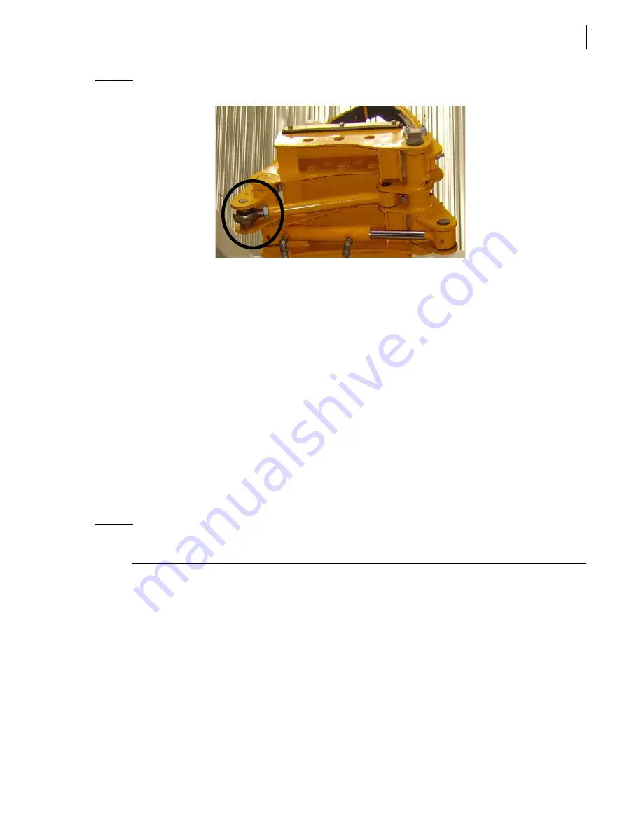
Figure 10-9 Adjusting adjustment rod
Bleeding Air Out of the Lifting Arm Hydraulic
Circuit
After opening the Helping Hand
TM
hydraulic circuit to replace (for example) a hydraulic cylinder or a
valve, air might enter into the hoses located between the arm control valve and the arm cylinder. As
the air cannot be completely removed by the normal use of the arm, the system must be bled.
The Helping Hand
TM
is composed of three hydraulic subcircuits, two of which must be bled
individually depending on the modifications done. Those subcircuits are the following:
Gripper hydraulic circuit
This subcircuit, which includes one cylinder (bore 1
1/2
in., stroke between 5 and 7
in.) and a valve,
controls the open/close motion of the gripper in order to grip containers.
In/Out hydraulic circuit
This subcircuit, which includes one cylinder (bore 1
1/2
in., stroke 54
in.) and a valve, controls the
extend/retract motion of the arm in order to reach containers and come back close to the truck for
travelling.
N
OTE
:
The Up/Down hydraulic circuit needs not to be bled because air that may be inside the circuit
can easily be removed by the normal use of the arm.
To bleed the gripper circuit:
1.
Apply all safety measures to ensure safety around the vehicle at all times and make sure to have
enough room to fully operate the arm and gripper.
2.
Make sure that the parking brake is applied.
3.
Slide out the arm about half way (gripper in the lower position and blades fully open).
Summary of Contents for MINIMAX
Page 1: ...MINIMAX TM MAINTENANCE MANUAL...
Page 2: ......
Page 3: ...MINIMAX MAINTENANCE MANUAL...
Page 8: ...vi Table of Contents Adjusting Arm Speed 164...
Page 30: ...22 Safety Figure 2 17 Drain valve on air tank...
Page 72: ...64 Lubrication Figure 4 10 Lubrication chart Helping Hand arm...
Page 80: ...72 Lubrication...
Page 90: ...82 Hydraulic System Figure 5 8 Oil temp level gauge Figure 5 9 Steel hydraulic tank...
Page 102: ...94 Hydraulic System Figure 5 21 Strainer assembly Strainer...
Page 106: ...98 Hydraulic System Figure 5 25 Detecting cylinder internal leaks 1 2 3 4 5 A A A...
Page 108: ...100 Hydraulic System...
Page 113: ...Electrical System 105 Electrical Schematics Cab Adaptation...
Page 114: ...106 Electrical System Cab Console Controls...
Page 115: ...Electrical System 107 Cab Controller...
Page 116: ...108 Electrical System Chassis...
Page 117: ...Electrical System 109 Body Module rear side...
Page 118: ...110 Electrical System Body Module front side...
Page 119: ...Electrical System 111 Tailgate Lighting...
Page 120: ...112 Electrical System Panic Bars Crusher Panel Tipper Interlocks...
Page 121: ...Electrical System 113 Cameras Switchpack Details Interlocks AUTO 10 SEC INHIBIT AUTO N AUTO ON...
Page 122: ...114 Electrical System...
Page 127: ...Troubleshooting 119 Figure 8 4 Ball end hex wrench metric and SAE...
Page 134: ...126 Troubleshooting Figure 8 6 Tailgate locking mechanism...
Page 156: ...148 Multiplexing...
Page 162: ...154 Multiplexing...
Page 164: ...156 Lifting Arm Figure 10 1 Mounting bolts Figure 10 2 Helping Hand gripper Figure 10 3 Hoses...


