


Lifting Arm
163
To adjust the end cushioning of the In/Out cylinder:
1.
Secure the arm working area using barrier tape or barricades.
2.
Put the transmission in neutral.
3.
Start the engine and engage the hydraulic pump.
4.
Fully extend and retract the Helping Hand
TM
to check if more cushioning is needed.
The arm should not hit hard at the end of its strokes. End of stroke cushioning should provide
smooth operation of the arm.
5.
If cushion adjustment is necessary, stop the hydraulic pump and turn off the engine.
6.
Tighten the corresponding adjustment screw to achieve a smoother movement at the end of the
stroke or loosen the screw if the movement is too slow (no shock should occur).
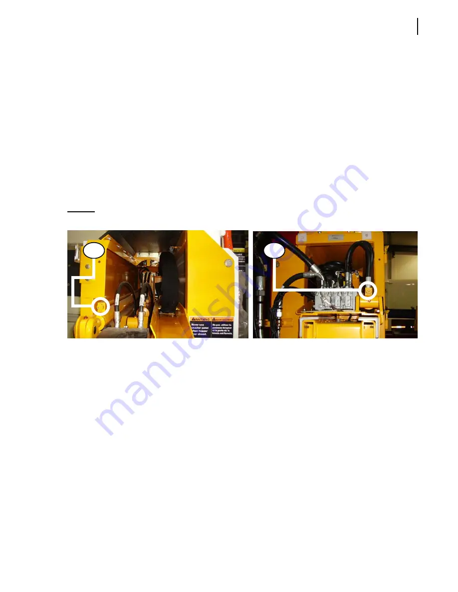
Use the adjustment screw on the curb side for the end-of-stroke extension motion (See A in
Figure 10-11); use the adjustment screw on the street side for the end-of-stroke retraction
motion (See B in Figure 10-11).
Figure 10-11 Cushion adjustment screws - In/Out cylinder (curb side: A; street side: B)
To adjust the end cushioning of the Up/Down cylinder:
1.
Secure the arm working area using barrier tape or barricades.
2.
Put the transmission in neutral.
3.
Start the engine and engage the hydraulic pump.
4.
Fully raise and lower the Helping Hand
TM
to check if more cushioning is needed.
The arm should not hit hard at the end of its strokes. End of stroke cushioning should provide
smooth operation of the arm.
5.
If cushion adjustment is necessary, stop the hydraulic pump and turn off the engine.
6.
Tighten the corresponding adjustment screw to achieve a smoother movement at the end of the
stroke or loosen the screw if the movement is too slow (no shock should occur).
Use the adjustment screw on the curb side for the end-of-stroke lowering motion (See A in
Figure 10-12); use the adjustment screw on the street side for the end-of-stroke raising motion
(See B in Figure 10-12).
A
B
Summary of Contents for MINIMAX
Page 1: ...MINIMAX TM MAINTENANCE MANUAL...
Page 2: ......
Page 3: ...MINIMAX MAINTENANCE MANUAL...
Page 8: ...vi Table of Contents Adjusting Arm Speed 164...
Page 30: ...22 Safety Figure 2 17 Drain valve on air tank...
Page 72: ...64 Lubrication Figure 4 10 Lubrication chart Helping Hand arm...
Page 80: ...72 Lubrication...
Page 90: ...82 Hydraulic System Figure 5 8 Oil temp level gauge Figure 5 9 Steel hydraulic tank...
Page 102: ...94 Hydraulic System Figure 5 21 Strainer assembly Strainer...
Page 106: ...98 Hydraulic System Figure 5 25 Detecting cylinder internal leaks 1 2 3 4 5 A A A...
Page 108: ...100 Hydraulic System...
Page 113: ...Electrical System 105 Electrical Schematics Cab Adaptation...
Page 114: ...106 Electrical System Cab Console Controls...
Page 115: ...Electrical System 107 Cab Controller...
Page 116: ...108 Electrical System Chassis...
Page 117: ...Electrical System 109 Body Module rear side...
Page 118: ...110 Electrical System Body Module front side...
Page 119: ...Electrical System 111 Tailgate Lighting...
Page 120: ...112 Electrical System Panic Bars Crusher Panel Tipper Interlocks...
Page 121: ...Electrical System 113 Cameras Switchpack Details Interlocks AUTO 10 SEC INHIBIT AUTO N AUTO ON...
Page 122: ...114 Electrical System...
Page 127: ...Troubleshooting 119 Figure 8 4 Ball end hex wrench metric and SAE...
Page 134: ...126 Troubleshooting Figure 8 6 Tailgate locking mechanism...
Page 156: ...148 Multiplexing...
Page 162: ...154 Multiplexing...
Page 164: ...156 Lifting Arm Figure 10 1 Mounting bolts Figure 10 2 Helping Hand gripper Figure 10 3 Hoses...


