28
General Cleanliness
Daily Cleaning of T
OP
S
ELECT
™ Body
After dumping all the recycling materials out of the T
OP
S
ELECT
™ body, perform the following
procedure:
N
OTE
:
For a T
OP
S
ELECT
™ unit with a Maximizer installed, proceed to page 97.
1.
Start the truck’s engine.
2.
Turn ON the pump switch.
3.
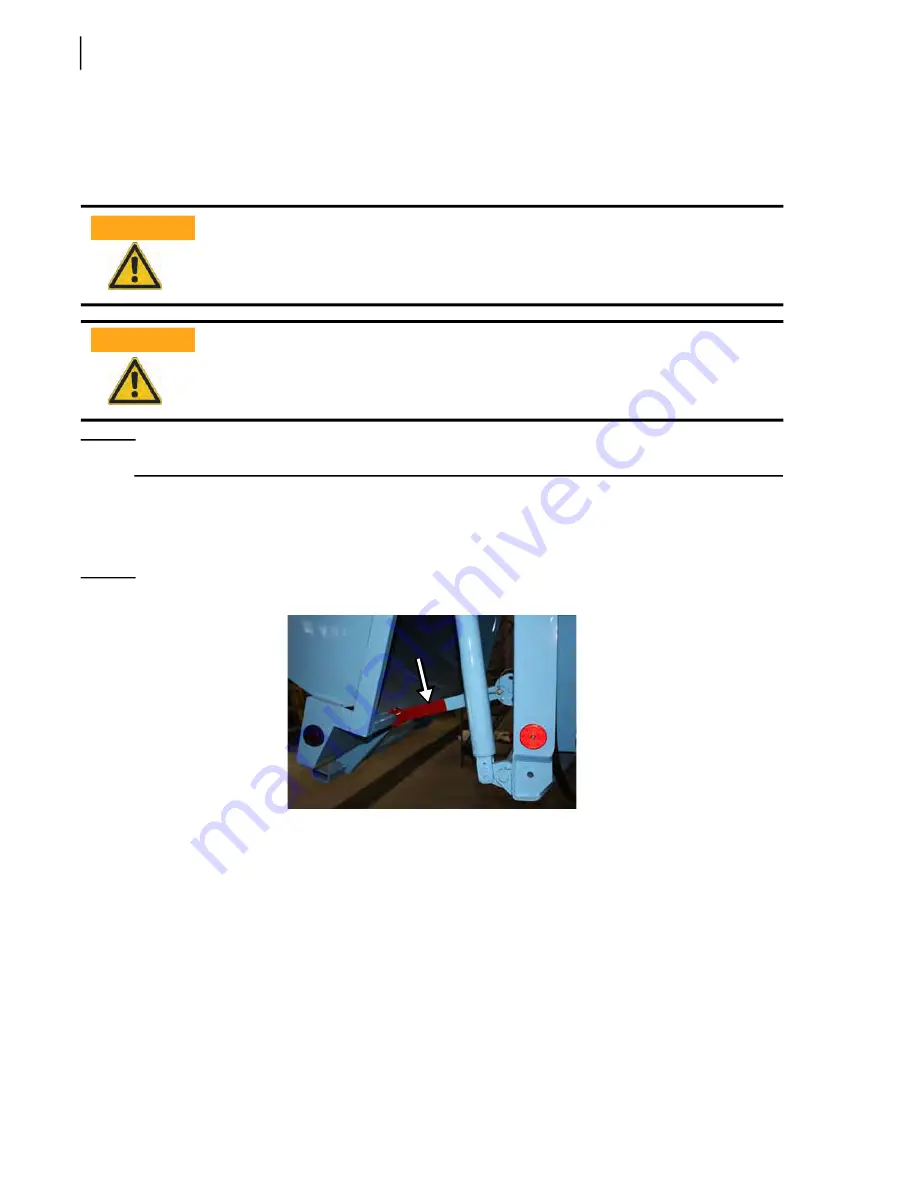
Open the tailgate enough to set the safety prop in place.
Figure 3
-
1 Tailgate safety prop
4.
Set the tailgate safety prop (see Figure 3
1).
5.
Raise the body about twelve (12) inches to help the water evacuate.
6.
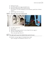
Lift the loading bucket(s) to open the roof.
7.
Install the loading bucket safety pins (see Figure 2
11).
8.
Turn OFF the pump switch.
9.
Stop the truck’s engine.
10.
Apply the Lockout/Tagout procedure (see
11.
Enter the body and proceed with the cleaning of the first partition (at the body front-end).
Using a shovel and a broom, remove as much residues as possible.
Use pressurized water to clean the rest.
Apply the Lockout/Tagout procedure before carrying out body cleaning operations.
Be sure to install the tailgate safety prop before entering the body.
WARNING!
WARNING!
Summary of Contents for Top Select
Page 1: ...TOP SELECT TM MAINTENANCE MANUAL...
Page 2: ......
Page 3: ...TOP SELECT MAINTENANCE MANUAL...
Page 8: ...vi Table of Contents...
Page 34: ...26 Safety...
Page 40: ...32 General Cleanliness...
Page 72: ...64 Loading Container Maintenance...
Page 104: ...96 Preventive Maintenance...
Page 121: ...Lubrication 113 Figure 11 2 Body hinges Grease Fittings on Body Figure 11 3 Tailgate and hooks...
Page 122: ...114 Lubrication Figure 11 4 Partition Figure 11 5 Optional Maximizer Location of lube zerks...
Page 123: ...Lubrication 115 Figure 11 6 Roof hinges and loading cylinders...
Page 124: ...116 Lubrication Figure 11 7 Lube chart...
Page 132: ...124 Troubleshooting...
Page 134: ...126 Hydraulic and Pneumatic Circuit Diagrams Hydraulic Schematics Single Side Bucket...
Page 135: ...Hydraulic and Pneumatic Circuit Diagrams 127 Single Side Bucket w Maximizer...
Page 136: ...128 Hydraulic and Pneumatic Circuit Diagrams Dual Side Bucket...
Page 137: ...Hydraulic and Pneumatic Circuit Diagrams 129 Dual Side Bucket w Maximizer...
Page 139: ...Hydraulic and Pneumatic Circuit Diagrams 131 Air System Schematics TS 1000 w Options...
Page 140: ...132 Hydraulic and Pneumatic Circuit Diagrams TS 2000 w Options...


