50
Loading Container Maintenance
• If the unloading angle is smaller than 45° when the bucket reaches the stoppers, you will need to
shorten the length of the rods to meet the angle requirement (angle must be set between 45°
and 50°).
• If the bucket slams on the sliding shoe on its way up, you will need to lengthen the rods to
correct this.
Once you reach a good compromise between those two references (that is the unloading angle and
the free course of the bucket), the adjustment process is completed.
N
OTE
:
Make sure to tack weld the locknuts once you are finished with the adjustment.
Adjusting Bucket Limit Switch
The backup alarm should sound as soon as the bucket starts moving. If this is not the case, you must
adjust the bucket limit switch using the following procedure.
To adjust the bucket limit switch:
1.
Raise the loading bucket and locate the corresponding limit switch.
2.
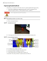
Use an Allen key to adjust the length and angle of the limit switch arm.
The limit switch must be adjusted in such a way that the backup alarm starts sounding as soon as
the loading bucket starts rising.
This safety feature is provided to warn people around to stay away from the vehicle to avoid
possible injury and to remind the operator that the loading bucket is still raised.
3.
Move the bucket up and down a few times to test the adjustment.
4.
Readjust if necessary.
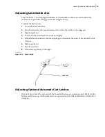
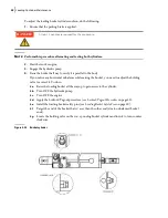
Figure 5
-
12 Bucket limit switch
Always apply the Lockout/Tagout procedure before doing any adjustment or repair (see
Adjust limit
switch at about
4½” from the
bottom rail
DANGER!
Summary of Contents for Top Select
Page 1: ...TOP SELECT TM MAINTENANCE MANUAL...
Page 2: ......
Page 3: ...TOP SELECT MAINTENANCE MANUAL...
Page 8: ...vi Table of Contents...
Page 34: ...26 Safety...
Page 40: ...32 General Cleanliness...
Page 72: ...64 Loading Container Maintenance...
Page 104: ...96 Preventive Maintenance...
Page 121: ...Lubrication 113 Figure 11 2 Body hinges Grease Fittings on Body Figure 11 3 Tailgate and hooks...
Page 122: ...114 Lubrication Figure 11 4 Partition Figure 11 5 Optional Maximizer Location of lube zerks...
Page 123: ...Lubrication 115 Figure 11 6 Roof hinges and loading cylinders...
Page 124: ...116 Lubrication Figure 11 7 Lube chart...
Page 132: ...124 Troubleshooting...
Page 134: ...126 Hydraulic and Pneumatic Circuit Diagrams Hydraulic Schematics Single Side Bucket...
Page 135: ...Hydraulic and Pneumatic Circuit Diagrams 127 Single Side Bucket w Maximizer...
Page 136: ...128 Hydraulic and Pneumatic Circuit Diagrams Dual Side Bucket...
Page 137: ...Hydraulic and Pneumatic Circuit Diagrams 129 Dual Side Bucket w Maximizer...
Page 139: ...Hydraulic and Pneumatic Circuit Diagrams 131 Air System Schematics TS 1000 w Options...
Page 140: ...132 Hydraulic and Pneumatic Circuit Diagrams TS 2000 w Options...


