Loading Container Maintenance
51
Adjusting Limit Switch Arm
Your T
OP
S
ELECT
™ unit is equipped with three (3) limit switches: each one is used to detect the
movement of a particular moving part: bucket, tailgate or body.
To adjust the limit switch:
1.
Loosen the limit switch nut.
2.
Move the lever arm to the approximate position where the switch is to be triggered.
3.
Tighten up the nut.
4.
To fine tune the adjustment, loosen the nut slightly.
5.
With a flathead screwdriver, turn the adjusting screw located at the center of the nut until a click
is heard.
6.
Tighten up the nut.
7.
Test the operation.
8.
If necessary, repeat steps 1 through 7.
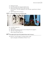
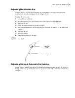
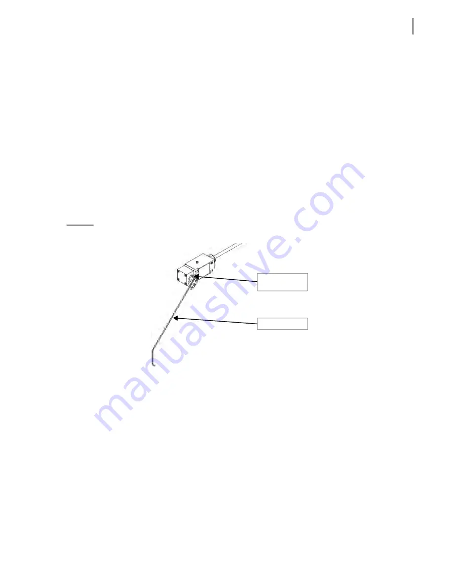
Figure 5
-
13 Limit switch
Adjusting Optional Automatic Cart Latches
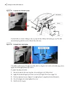
On a daily basis check all components of the bucket latch system are working properly. Make sure the
latch goes all the way up. A failure may lead to an operator injury if a fully-loaded roller cart falls off on
its way up.
Adjustment
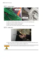
screw
Lever arm
Summary of Contents for Top Select
Page 1: ...TOP SELECT TM MAINTENANCE MANUAL...
Page 2: ......
Page 3: ...TOP SELECT MAINTENANCE MANUAL...
Page 8: ...vi Table of Contents...
Page 34: ...26 Safety...
Page 40: ...32 General Cleanliness...
Page 72: ...64 Loading Container Maintenance...
Page 104: ...96 Preventive Maintenance...
Page 121: ...Lubrication 113 Figure 11 2 Body hinges Grease Fittings on Body Figure 11 3 Tailgate and hooks...
Page 122: ...114 Lubrication Figure 11 4 Partition Figure 11 5 Optional Maximizer Location of lube zerks...
Page 123: ...Lubrication 115 Figure 11 6 Roof hinges and loading cylinders...
Page 124: ...116 Lubrication Figure 11 7 Lube chart...
Page 132: ...124 Troubleshooting...
Page 134: ...126 Hydraulic and Pneumatic Circuit Diagrams Hydraulic Schematics Single Side Bucket...
Page 135: ...Hydraulic and Pneumatic Circuit Diagrams 127 Single Side Bucket w Maximizer...
Page 136: ...128 Hydraulic and Pneumatic Circuit Diagrams Dual Side Bucket...
Page 137: ...Hydraulic and Pneumatic Circuit Diagrams 129 Dual Side Bucket w Maximizer...
Page 139: ...Hydraulic and Pneumatic Circuit Diagrams 131 Air System Schematics TS 1000 w Options...
Page 140: ...132 Hydraulic and Pneumatic Circuit Diagrams TS 2000 w Options...


