Hydraulic System Maintenance
81
Replacing Filter Elements
N
OTE
:
To protect new components of the hydraulic system, the return filter element must be changed
after the
first
50 hours of operation of the vehicle. Change the element twice a year afterwards.
This will help keep the oil clean, extend component life and reduce breakdowns.
To replace the hydraulic filter:
1.
Ensure that the parking brake is applied.
2.
Lock out and tag out the vehicle (see
3.
Prepare a pan or a bucket to collect the oil that will come out of the filter housing (two gallons of
oil).
4.
Also, have a filter wrench and a new filter element within your reach.
5.
Remove the filter element.
The return filter system contains a check valve that closes when the cartridge is removed, thus
preventing the whole tank from draining.
6.
Replace the filter element with a new one.
7.
Be sure to hand tight the new filter.
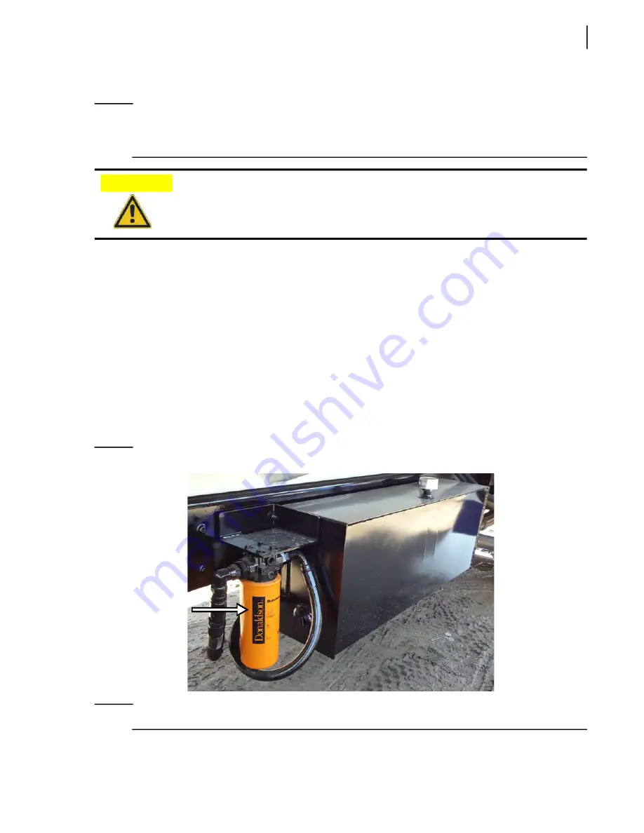
Figure 7
-
10 Filter element
N
OTE
:
The filter must be correctly “hand-tightened”.
Change the return filter element after the first 50 hours of operation.
CAUTION!
Summary of Contents for Top Select
Page 1: ...TOP SELECT TM MAINTENANCE MANUAL...
Page 2: ......
Page 3: ...TOP SELECT MAINTENANCE MANUAL...
Page 8: ...vi Table of Contents...
Page 34: ...26 Safety...
Page 40: ...32 General Cleanliness...
Page 72: ...64 Loading Container Maintenance...
Page 104: ...96 Preventive Maintenance...
Page 121: ...Lubrication 113 Figure 11 2 Body hinges Grease Fittings on Body Figure 11 3 Tailgate and hooks...
Page 122: ...114 Lubrication Figure 11 4 Partition Figure 11 5 Optional Maximizer Location of lube zerks...
Page 123: ...Lubrication 115 Figure 11 6 Roof hinges and loading cylinders...
Page 124: ...116 Lubrication Figure 11 7 Lube chart...
Page 132: ...124 Troubleshooting...
Page 134: ...126 Hydraulic and Pneumatic Circuit Diagrams Hydraulic Schematics Single Side Bucket...
Page 135: ...Hydraulic and Pneumatic Circuit Diagrams 127 Single Side Bucket w Maximizer...
Page 136: ...128 Hydraulic and Pneumatic Circuit Diagrams Dual Side Bucket...
Page 137: ...Hydraulic and Pneumatic Circuit Diagrams 129 Dual Side Bucket w Maximizer...
Page 139: ...Hydraulic and Pneumatic Circuit Diagrams 131 Air System Schematics TS 1000 w Options...
Page 140: ...132 Hydraulic and Pneumatic Circuit Diagrams TS 2000 w Options...

