122
Troubleshooting
Detecting Internal Leak in Cylinders
An internal leak is caused by a damaged seal inside the hydraulic cylinder (see #1 in Figure 12
1).
Because the cylinder is leaking oil inside (bypassing), a certain amount of pressure is lost, reducing
the efficiency of the cylinder and its capacity to push and/or pull.
No control on all
cylinders
Hydraulic system off
Engage the hydraulic system
Slipping clutch
Oil supply
All or any of the following:
- Replace filter (see page 81)
- Clean supply line
- Change hydraulic oil
- Hydraulic oil is too cold
No flow or pressure
See “Pump-Related Problems” Table
above
Contaminated oil
Change filter and oil (see
on page 78 and
Wrong type of oil
Change filter and oil (see
on page 78 and
Faulty control valve
Repair, adjust or replace
Wrong relief pressure setting
Check for proper adjustment of the relief
valve
CYLINDER-RELATED PROBLEMS
Problem
Cause
Remedy
Summary of Contents for Top Select
Page 1: ...TOP SELECT TM MAINTENANCE MANUAL...
Page 2: ......
Page 3: ...TOP SELECT MAINTENANCE MANUAL...
Page 8: ...vi Table of Contents...
Page 34: ...26 Safety...
Page 40: ...32 General Cleanliness...
Page 72: ...64 Loading Container Maintenance...
Page 104: ...96 Preventive Maintenance...
Page 121: ...Lubrication 113 Figure 11 2 Body hinges Grease Fittings on Body Figure 11 3 Tailgate and hooks...
Page 122: ...114 Lubrication Figure 11 4 Partition Figure 11 5 Optional Maximizer Location of lube zerks...
Page 123: ...Lubrication 115 Figure 11 6 Roof hinges and loading cylinders...
Page 124: ...116 Lubrication Figure 11 7 Lube chart...
Page 132: ...124 Troubleshooting...
Page 134: ...126 Hydraulic and Pneumatic Circuit Diagrams Hydraulic Schematics Single Side Bucket...
Page 135: ...Hydraulic and Pneumatic Circuit Diagrams 127 Single Side Bucket w Maximizer...
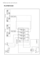
Page 136: ...128 Hydraulic and Pneumatic Circuit Diagrams Dual Side Bucket...
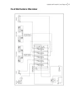
Page 137: ...Hydraulic and Pneumatic Circuit Diagrams 129 Dual Side Bucket w Maximizer...
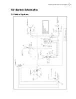
Page 139: ...Hydraulic and Pneumatic Circuit Diagrams 131 Air System Schematics TS 1000 w Options...
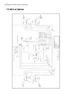
Page 140: ...132 Hydraulic and Pneumatic Circuit Diagrams TS 2000 w Options...


