20
Safety
Figure 2
-
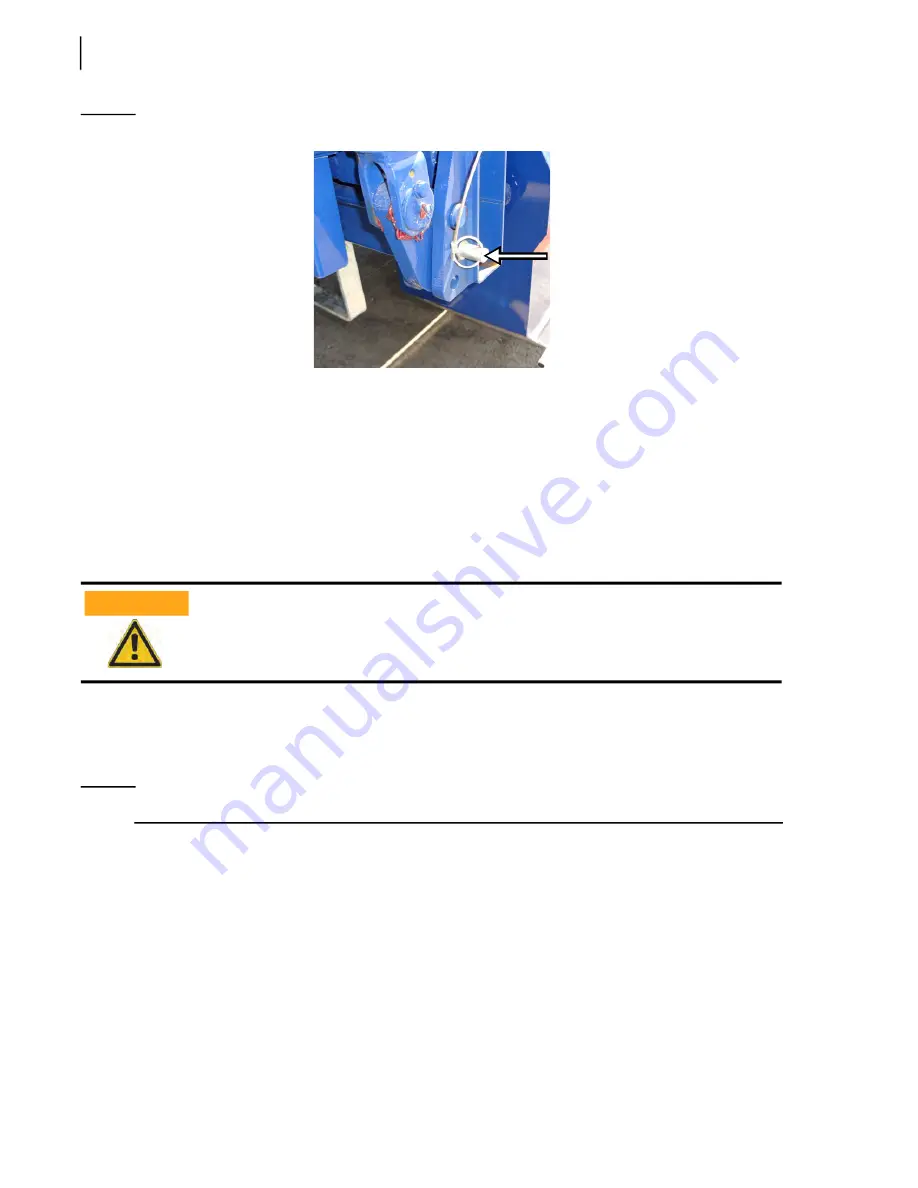
9 Tailgate safety pin in storage position
Loading Bucket Safety Pins
The loading bucket can be locked and secured at the end of its tracks (Figure 2
11)
to allow access to the chassis components.
The upper parts of the unit should be accessed by maintenance personnel only and must be reached
only with a guarded platform that meets OSHA regulations regarding elevated working stations.
Once engaged, the safety pins mechanically prevent any unwanted downward movement of the
loading bucket.
To install the loading bucket safety pin:
1.
Start the truck’s engine.
2.
Turn ON the pump switch to engage the hydraulic system.
N
OTE
:
Loading bucket has to be empty and in rest down position. Unload prior to continuing.
3.
Lift the bucket until it is in full dump position.
4.
Turn OFF the pump switch.
5.
Stop the engine.
6.
Apply the Lockout/Tagout procedure (see
7.
Use a ladder to climb and get to where the safety pins are in stored position, then remove them.
Always install the safety pins in both front and rear loading tracks.
WARNING!
Summary of Contents for Top Select
Page 1: ...TOP SELECT TM MAINTENANCE MANUAL...
Page 2: ......
Page 3: ...TOP SELECT MAINTENANCE MANUAL...
Page 8: ...vi Table of Contents...
Page 34: ...26 Safety...
Page 40: ...32 General Cleanliness...
Page 72: ...64 Loading Container Maintenance...
Page 104: ...96 Preventive Maintenance...
Page 121: ...Lubrication 113 Figure 11 2 Body hinges Grease Fittings on Body Figure 11 3 Tailgate and hooks...
Page 122: ...114 Lubrication Figure 11 4 Partition Figure 11 5 Optional Maximizer Location of lube zerks...
Page 123: ...Lubrication 115 Figure 11 6 Roof hinges and loading cylinders...
Page 124: ...116 Lubrication Figure 11 7 Lube chart...
Page 132: ...124 Troubleshooting...
Page 134: ...126 Hydraulic and Pneumatic Circuit Diagrams Hydraulic Schematics Single Side Bucket...
Page 135: ...Hydraulic and Pneumatic Circuit Diagrams 127 Single Side Bucket w Maximizer...
Page 136: ...128 Hydraulic and Pneumatic Circuit Diagrams Dual Side Bucket...
Page 137: ...Hydraulic and Pneumatic Circuit Diagrams 129 Dual Side Bucket w Maximizer...
Page 139: ...Hydraulic and Pneumatic Circuit Diagrams 131 Air System Schematics TS 1000 w Options...
Page 140: ...132 Hydraulic and Pneumatic Circuit Diagrams TS 2000 w Options...


