Monthly Visual Inspection
37
8.
Turn OFF the pump switch.
9.
Stop the engine.
10.
Apply the Lockout/Tagout procedure (see
11.
Take a ladder of appropriate size and bring it close to the front roof lifting beam.
12.
Climb up to inspect the front cylinder.
13.
Check for dirt on the front beam.
If you find some, determine if that dirt is of greasy type. If so, refer to the
Troubleshooting
section.
14.
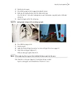
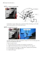
If a spillage deflector is present (Figure 4
6), make sure it is not ripped.
15.
Visually inspect the weld on the lifting beam.
16.
Repeat Steps 11 - 15 for the bucket back end.
17.
If your T
OP
S
ELECT
™ unit has two buckets, repeat Steps 2 - 16 for the other bucket.
Figure 4
-
6 Spillage deflector
Visual Inspection of the Tailgate
To perform the visual inspection of the tailgate, apply the following procedure:
1.
Follow the three preparation steps as described on page 33 before carrying out the visual
inspection operations.
2.
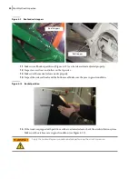
Inspect the welding area around the hinges.
3.
Check tailgate hinges and pins.
Always set the tailgate safety prop when the tailgate is open for inspection or maintenance
purposes.
Always use the tailgate safety prop when working under a raised tailgate. The prop must be
used even if the tailgate is fully raised. Failure to do so may cause serious injury or even
death.
WARNING!
WARNING!
Summary of Contents for Top Select
Page 1: ...TOP SELECT TM MAINTENANCE MANUAL...
Page 2: ......
Page 3: ...TOP SELECT MAINTENANCE MANUAL...
Page 8: ...vi Table of Contents...
Page 34: ...26 Safety...
Page 40: ...32 General Cleanliness...
Page 72: ...64 Loading Container Maintenance...
Page 104: ...96 Preventive Maintenance...
Page 121: ...Lubrication 113 Figure 11 2 Body hinges Grease Fittings on Body Figure 11 3 Tailgate and hooks...
Page 122: ...114 Lubrication Figure 11 4 Partition Figure 11 5 Optional Maximizer Location of lube zerks...
Page 123: ...Lubrication 115 Figure 11 6 Roof hinges and loading cylinders...
Page 124: ...116 Lubrication Figure 11 7 Lube chart...
Page 132: ...124 Troubleshooting...
Page 134: ...126 Hydraulic and Pneumatic Circuit Diagrams Hydraulic Schematics Single Side Bucket...
Page 135: ...Hydraulic and Pneumatic Circuit Diagrams 127 Single Side Bucket w Maximizer...
Page 136: ...128 Hydraulic and Pneumatic Circuit Diagrams Dual Side Bucket...
Page 137: ...Hydraulic and Pneumatic Circuit Diagrams 129 Dual Side Bucket w Maximizer...
Page 139: ...Hydraulic and Pneumatic Circuit Diagrams 131 Air System Schematics TS 1000 w Options...
Page 140: ...132 Hydraulic and Pneumatic Circuit Diagrams TS 2000 w Options...


