48
Loading Container Maintenance
Replacing Bucket Rod Ends
If maintenance or replacement of the bucket rod ends is required, apply the following procedure:
1.
Ensure that the parking brake is applied and the vehicle is locked out and tagged out for
maintenance purposes. Refer to “Lockout/Tagout Procedure” on page 22.
N
OTE
:
Perform this procedure on one rod at a time.
2.
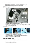
Place a jack under the bucket.
Figure 5
-
9 Jack placed under bucket
3.
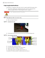
On the upper end of the rod, remove the cotter pin, pin, lock bolt and spring washer.
Figure 5
-
10 Rod end attachment hardware
4.
Lower the rod by swiveling it downward.
5.
Loosen the locknut and unwind to remove the rod end.
6.
Perform maintenance or reinstall a new rod end.
7.
Reverse this procedure to reinstall the upper end of the rod.
You can refer to the above procedure to remove the lower end of the rod.
At least 2 people are required for this procedure.
Pin
Lock bolt
Cotter pin
Rod end
Locknut
Spring washer
DANGER!
Summary of Contents for Top Select
Page 1: ...TOP SELECT TM MAINTENANCE MANUAL...
Page 2: ......
Page 3: ...TOP SELECT MAINTENANCE MANUAL...
Page 8: ...vi Table of Contents...
Page 34: ...26 Safety...
Page 40: ...32 General Cleanliness...
Page 72: ...64 Loading Container Maintenance...
Page 104: ...96 Preventive Maintenance...
Page 121: ...Lubrication 113 Figure 11 2 Body hinges Grease Fittings on Body Figure 11 3 Tailgate and hooks...
Page 122: ...114 Lubrication Figure 11 4 Partition Figure 11 5 Optional Maximizer Location of lube zerks...
Page 123: ...Lubrication 115 Figure 11 6 Roof hinges and loading cylinders...
Page 124: ...116 Lubrication Figure 11 7 Lube chart...
Page 132: ...124 Troubleshooting...
Page 134: ...126 Hydraulic and Pneumatic Circuit Diagrams Hydraulic Schematics Single Side Bucket...
Page 135: ...Hydraulic and Pneumatic Circuit Diagrams 127 Single Side Bucket w Maximizer...
Page 136: ...128 Hydraulic and Pneumatic Circuit Diagrams Dual Side Bucket...
Page 137: ...Hydraulic and Pneumatic Circuit Diagrams 129 Dual Side Bucket w Maximizer...
Page 139: ...Hydraulic and Pneumatic Circuit Diagrams 131 Air System Schematics TS 1000 w Options...
Page 140: ...132 Hydraulic and Pneumatic Circuit Diagrams TS 2000 w Options...


