6 |
S u r e K e y M a n u a l
Preparation
Do it step by step to start using SureKey! You can also take a look at our video manuals.
Step 1: Mounting the key inside SureKey
To see if your SureKey works correctly before the assembly, we recommend placing the battery in the insert and
sliding it inside. A properly working device generates a short sound signal.
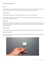
1.
Slide the battery casing inside the key cover.
2.
Place the key cover vertically in the mounting socket included in the packaging
–
with the key slot pointing up.
3.
Before the assembly, make sure that the key fits inside SureKey and, if needed
–
clean
the key’s surface.
4.
Apply a rubber band on the key (wrap it around a
few times) where the “toothed part” starts –
right below the
key’s bow. The rubber help
s
control the key’s level.
5.
Open the glue, place the mixer on the tip and carefully apply the adequate amount of glue by inserting the end
of the mixer into the key’s chamber.
Warning! The amount of glue applied depends on the key’s size
,
and the glue shouldn’t be used in its
entirety, as it would cause the excess glue to ooze out. The formula below helps to determine the right
amount of glue depending on the size of the key’s bow. The percentage of the glue used specifies how
much of the glue should be applied inside before putting the key in.
Amount of glue = 3300 - (W x H x D)
Percentage used = Amount of glue/4000
W
–
the width of the key’s bow *mm+
H
–
the height of the key’s bow *mm+
D
–
the depth of the key’s bow *m
m]
For instance, a key-
sized 20x20x2 only requires slightly above half of the container’s
contents (~60%). The bigger the size of the key’s bow, the less of the glue should be
used.
6.
Slowly place the key inside SureKey, adjusting the correct location until the glue sets (about 10-20 minutes).
After that time, wait for another 10-20 minutes
with the battery insert out. It is essential for the key’s position
relative to the insert to be as perpendicular to the casing’s edge as possible. Otherwise detecting the lock’s state
might be impossible.
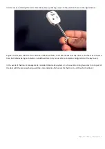
7.
Place the attached CR2016 battery in the battery insert, as per the figure, making sure the battery is correctly
polarized
–
the label with + . Then put the battery insert back inside the SureKey.
Step 2: Configuration
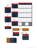
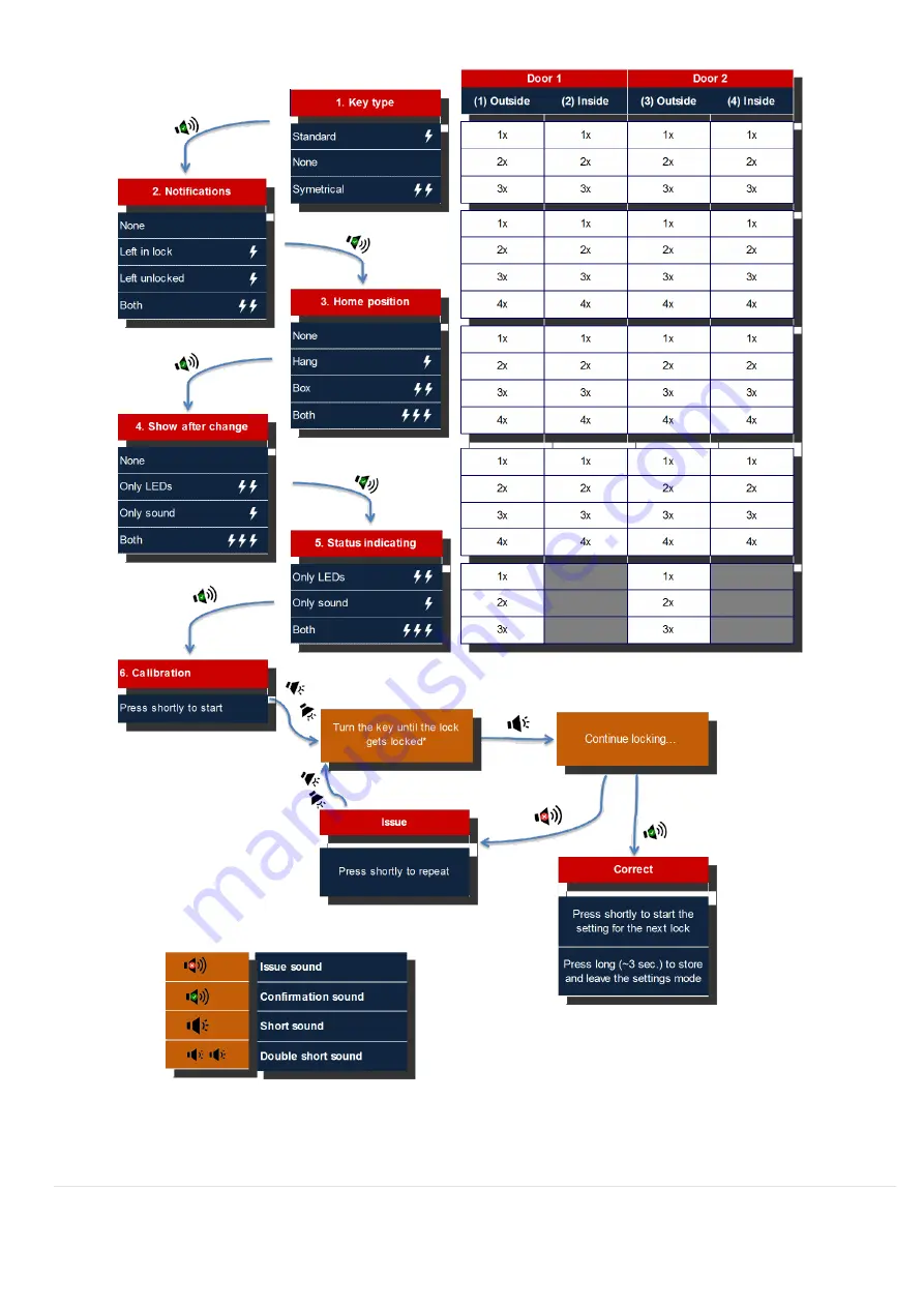
Use the button located in the upper part of the SureKey for changing the settings. Hold the button to enter the
settings mode (the best choice for this task is a ballpoint pen or other object with a narrow tip - WARNING! The button
has only to be pressed until it clicks - pressing too hard might damage the configuration button) for about 3 seconds
–
entering the settings mode is indicating with a loud sound signal. Warning! After 40 seconds without activity, the
settings mode stops automatically. That’s why, to perform the configuration correctly, check the manual and fill out the
table with selected settings before the configuration so that you can use your SureKey faster!
7 |
S u r e K e y M a n u a l


