

INSTALLER’S MANUAL
CORMATIN
Page 9 of 40
In case of use with a gas other than that for which the
appliance was initially set up, it is
crucial
to replace the
orifices and modify the adjustments as defined below.
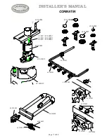
TOP BURNERS
Orifice
Lift the air ring
E
. Replace the injectors
F
in accordance with
Table 3 and Figure 14 (Ø in 1/100 mm).
The side burner bodies are kept in place by a transversal bar
(
H
, fig. 16). In order to take them out, unscrew screws
I
(fig.
17) then
G
(fig. 15).
Note
:
When one or more nozzles are changed, the sealing
ring should be changed as well (see gas circuit diagram).
Adjustment of primary air
Put body & cap back on their respective burners, set air ring
E
by
sliding it from bottom to top (fig. 14, Table 4).
Note :
Normal flames are bluish green except for natural gas flames
which are violet.
L.P. propane
Natural gas
Fig. 13
Clé de 12
Wrench 12 (
15
/
32
)
Fig. 14
F
E
Clé de 3
Wrench 3 (
1
/
8
)
Fig. 15
G
I
Fig. 17
Clé de 7
Wrench 12 (
15
/
32
)
H
Fig. 16