MANUEL D’INSTALLATION
INSTALLER’S MANUAL
MÂCON
Page 13 sur 43– FT138a – FR / GB – Date de mise à jour : 02/02/04- Indice : 03
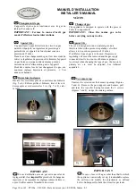
Fig. 15
OVEN BURNER
GB
Oven orifice (all ovens)
Remove the base,
CAUTION:
when refitting place the
base underneath the groove on the fascia (Figure 15).
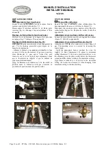
Disconnect the connection piece, unscrew screw
K
on the
orifice holder (Figure 16). Replace the orifice (Table
8
in
appendix
0
).
Adjustment of oven primary airflow (all ovens )
Loosen the screw that secures the air ring and then adjust
(Figure 17, Table
8
in appendix
0
).
Adjustment of oven reduced flowrate (fig. 18)
Adjustment is
VITAL
after connection or any change of
gas. The adjusting screw is accessed by removing the
control knob.
- Light the appropriate burner, pre-heat the oven for
roughly 1/4 hour (thermostat 10), adjust to minimum
setting (thermostat 1), then use a small screwdriver to set
the adjusting screw (do this quickly before the thermostat
responds and the burner returns to the maximum setting).
Note: flame is reduced to ¼ of its size in the maximum
setting, the burner must remain lit when changing from
maximum setting to minimum setting.
BRÛLEUR DE FOUR
FR
Injecteur de four (tous fours)
Retirer la sole,
ATTENTION
lors de la repose, bien la
ramener sous le pli de la façade (fig. 15)
Désaccoupler la tubulure, dévisser la vis
K
du porte
injecteur (fig. 16). Echanger l’injecteur (tableau n°
8
en
annexe
0
).
Réglage de l’air primaire four( tous fours )
Dévisser la vis de maintien de la bague d’air, procéder
au réglage (fig. 17, tableau n°
8
en annexe
0
).
Réglage du débit réduit de four (fig. 18)
IMPERATIF
après raccordement et tout changement de
gaz.. Vis de réglage accessible après dépose de la
manette de commande.
- Allumer le brûleur correspondant, préchauffer le four
environ 1/4 d’heure (thermostat 10), passer en position
mini (thermostat 1), puis agir à l’aide d’un petit
tournevis sur la vis de réglage (agir rapidement avant
que le thermostat ne réagisse et que le brûleur ne
repasse au débit maximum).
Nota: les flammes sont réduites au ¼ de leur taille en
position maxi, le brûleur ne doit pas s’éteindre en
passant de la position maxi à la position mini.
Fig. 16
K
Fig. 17
Fig. 18


