background image


Page 13 of 17 – US – 

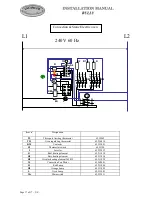
GAS CIRCUIT DIAGRAMME
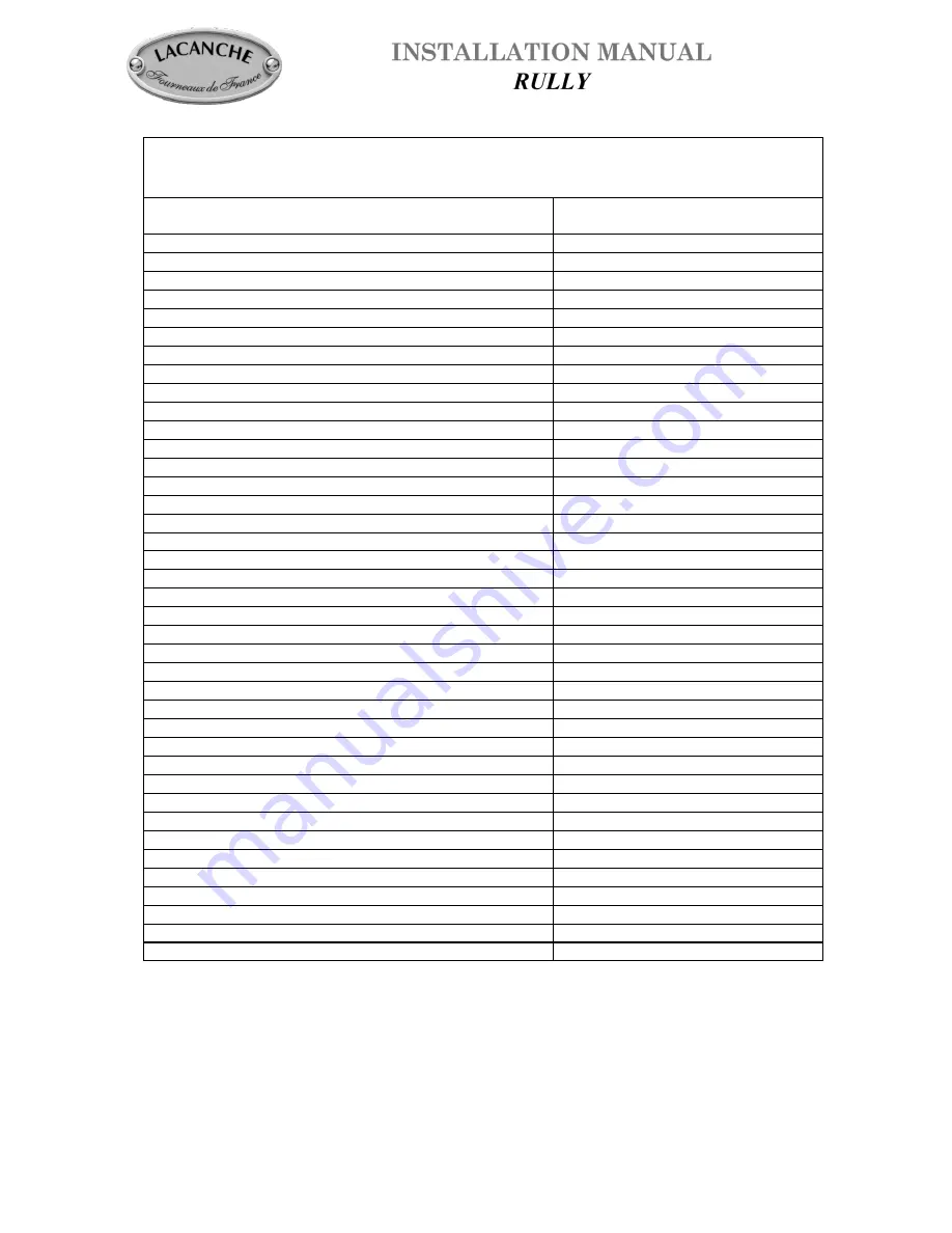


Designation 


Part number  

Burner cap 1,5 kW 

65.330004 

Burner cap 3,0 W 

65.330005 

Burner cap 4,0 kW 

65.330006 

Burner cap 5,0 kW 

65.330007 

Burner bowl 1,5 kW 

65.640008 

Burner bowl 3,0 kW 

65.640004 

Burner bowl 4,0 kW 

65.640005 

Burner bowl 5,0 kW 

65.640006 

Air Shuttler 

65.080005 

Mixing tube (1,5-3,0-4,0 & 5,0 kW) 

65.064007 

Injector holder 

65.033018 

Sealing ring 

65.430007 

Injector Dia. 65 

65.14964 

Injector Dia. 90 

65.14969 

Injector Dia. 95 

65.14970 

Injector Dia. 105 

65.52863 

Injector Dia. 120 

65.14973 

Injector Dia. 130 

65.14974 

Injector Dia. 140 

65.14975 

Injector Dia. 145 

65.27781 

Injector Dia. 170 

65.30546 

Brass knob (Gas model) 

65.044013 

Chrome knob (Gas model) 

65.044014 

Brass knob (Elec. model) 

65.044015 

Chrome knob (Elec. model) 

65.044016 

Regulator 

65.103023 

All oven burner 

73.062010 

Injector holder 

65.51764 

Screw 

65.51085 

Reducing fitting 

65.129099 

switch 

65.28979 

Thermocouple 

65.103024 

Pilot burner LP 

65.103032 

Pilot burner NG 

65.103031 

Oven electrode 

65.103004 

Spiggott rod 

59.907379 

Oven thermostat 

65.53670 

Top burner valve 

65.103029 

Oven burner valve 

65.103033 


Summary of Contents for RULLY

Page 1: ...ully INSTALLATION MANUAL Appliances must be installed in a workmanlike manner in accordance with the instructions in this manual and locally applicable regulations This manual will be handed over to t...

Page 2: ...Page 2 of 17 US...

Page 3: ...acent base cabinet countertop surface Min clearances to combustibles 0 0 mm from rear with spacer installed 0 0 mm from sides below countertop surface height 2 51 mm from sides above countertop surfac...

Page 4: ...time of the order the appliance will be built to use the specified gas type No further work is required by the installer Fig 3 B IMPORTANT Manual shut off valve should be installed in an accessible lo...

Page 5: ...the hob to gain access to the pressure regulator remove the top Convertible Regulator The reversible cap is labeled either LP or NAT and is easily recognized by the raised center screw slot for natura...

Page 6: ...changed the sealing ring should be changed as well see gas circuit diagram Adjustment of primary air Refit the burner bodies and burner caps in their respective recesses adjust the air ring E of the...

Page 7: ...oking surface When refitting the cooking surface it is vital to tighten fastening screws figures 4 5 and 6 Failure to do so can cause distortion of the cooking surface OVEN BURNERS Disassembling of th...

Page 8: ...embly Unscrew pilot injector Replace new injector Table 5 screw in completely until injector bottoms out Replace cap screw Gas pilot LP 65 103032 Gas pilot NG 65 103031 Table 5 GAS Pressure Oven Pilot...

Page 9: ...utral use a 4 wire power supply cord or pigtail kit Cord must be agency approved for use with household ranges Remove access door O P Figure 22 23 Connect to terminal block in accordance with figure 2...

Page 10: ...lied with the appliance Screw the wall spacer to the range according to figure 26 with the thumbscrews and hardware provided Then move the range backwards into position This spacer is reversible to pr...

Page 11: ...e along the seam that the bracket can be freely inserted Figure 2 Mounting screws are not provided This bracket is designed to be mounted to a load bearing support such as a wall stud This anti tip de...

Page 12: ...mple SILICAL GEL BARBAHL Caution Any excess grease should be removed Reverse operation 3 to 1 in that order to put valve and knob back on SAFETY OVERLIMIT THERMOSTAT This purely mechanical switch gove...

Page 13: ...14969 Injector Dia 95 65 14970 Injector Dia 105 65 52863 Injector Dia 120 65 14973 Injector Dia 130 65 14974 Injector Dia 140 65 14975 Injector Dia 145 65 27781 Injector Dia 170 65 30546 Brass knob Ga...

Page 14: ...Page 14 of 17 US 65 39895 65 226006 65 080005 65 033018 1 5 kW 65 064007 3 0 kW 65 064007 4 0 kW 65 064007 5 0 kW 65 064007 65 103029 4 screws 65 129101 4 disc 65 30932 65 103033...

Page 15: ...Page 15 of 17 US D tail A D tail B 65 103032 LP 65 103031 NG 65 103029 65 103033 65 103033...

Page 16: ...ation B Top burner electrode 65 226006 S1 Switch 65 103030 120 V 60 Hz N L1 GR S HT N 4 L 5 HT N 4 L 5 GR S HT N 4 L 5 HT N 4 L 5 GR Top burners code A E 5 N D T I C 01 02 03 0O 0T gas grill code 0Y H...

Page 17: ...2 Circular heating element 2650 W 65 211028 M Convection Fan Motor 65 260001 H Red Lamp 65 231004 H1 Orange Lamp 65 231005 L Oven Lamp 65 232003 Mr Microswitch 65 222011 L1 T1 L2 T2 L3 T3 L4 T4 L1 T1...

Reviews: