Page 4 of 17 – US –
Before connection
:
Check:
- Pipework is perfectly clean in order to prevent the injectors
becoming blocked and malfunctioning of the magnetic heads.
- The gas for which the appliance was set up: Rating plate and
markings.
- Cross-sectional area of gas supply pipework is compatible with the
appliance’s thermal output.
- Provide adequate air supply during use of the appliance.
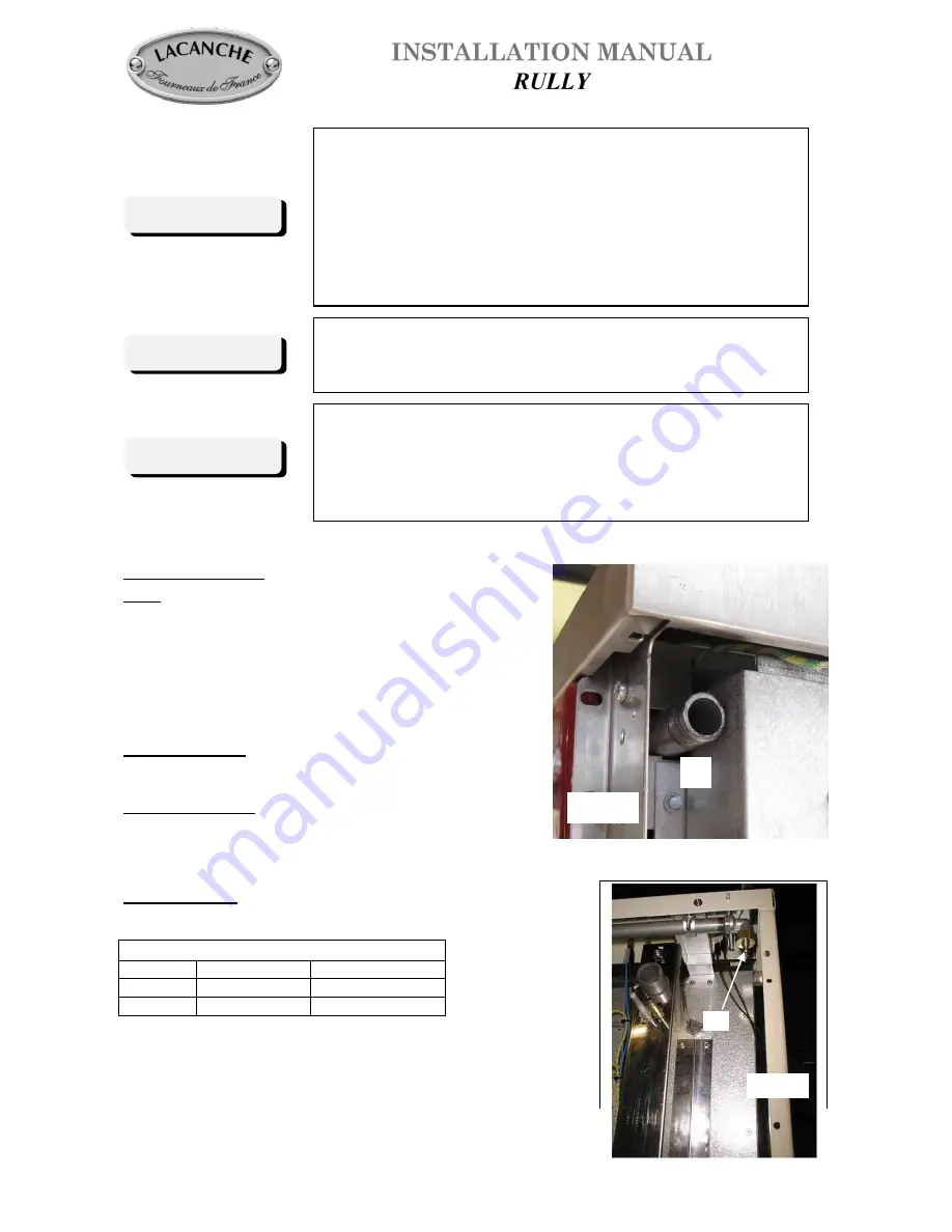
Gas connection
:
Female coupling Ø 15/21, 1/2” ID NPT on
A
(Figure 2).
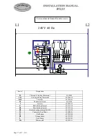
After connection:
Check/test the manifold pressure on pressure connection Ø 15/21,
1/8” NPT on
B
(Figure 3, Table 2).
Change of gas:
The appliance is designed to operate with the gases in Table 2.
Table 2
Country
GAS
Pressure (Pn)
U.S.
Natural gas
6’’ WC
U.S.
L.P. propane
10’’ WC
If specified at the time of the order, the appliance will
be built to use the specified gas type. No further
work is required by the installer.
Fig. 3
B
IMPORTANT
Manual shut-off valve should be installed in an accessible
location in the gas piping external to the appliance for the
purpose of turning on or shutting off gas to the appliance.
A location at the back of an adjacent cabinet is
recommended.
THE
APPLIANCE
MUST
BE
INSTALLED
IN
ACCORDANCE WITH THE LOCAL CODES OR
National Fuel Gas Code, ANSI Z223.1 or latest edition.
IMPORTANT
Recommended to be installed under an exhaust hood.
In the commonwealth of Massachusetts, the appliance must
be installed by a licensed plumber or gas fitter.
Do not install this unit near combustible walls, partitions,
pieces of furniture or decorative material unless these are
covered by adequate material of the non-combustible type.
Making sure the resulting installation meets fire
regulations.
IMPORTANT
Fig. 2
A