background image


Page 9 of 17 – US – 


Fig. 23 

ELECTRICAL 


 It is hazardous to put the appliance into service without connecting it to suitable ground. 

No liability can be accepted for accidents resulting from non-compliance with this requirement or incorrect grounding.  




Before connection, check that the

Mains voltage is compatible with the appliance’s rated voltage and thermal output.  


A power cord has been installed by the importer / 
distributer.  DO NOT remove this cord. 
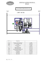


Connection: 

-


Use  a  4-wire  cord  rated  for  30A  (NEMA  14-30P)  or  50A  (NEMA  14-50P) 
120/240 VAC, type SRD, SRDT, S, SO or ST.  

-


Where local Codes do not permit grounding through neutral, use a 4-wire power 
supply cord or “pigtail” kit. Cord must be agency approved for use with household ranges. 

-


Remove access door 

O, P

 (Figure.22 & 23). 

-


Connect to terminal block in accordance with figure 24. 

-


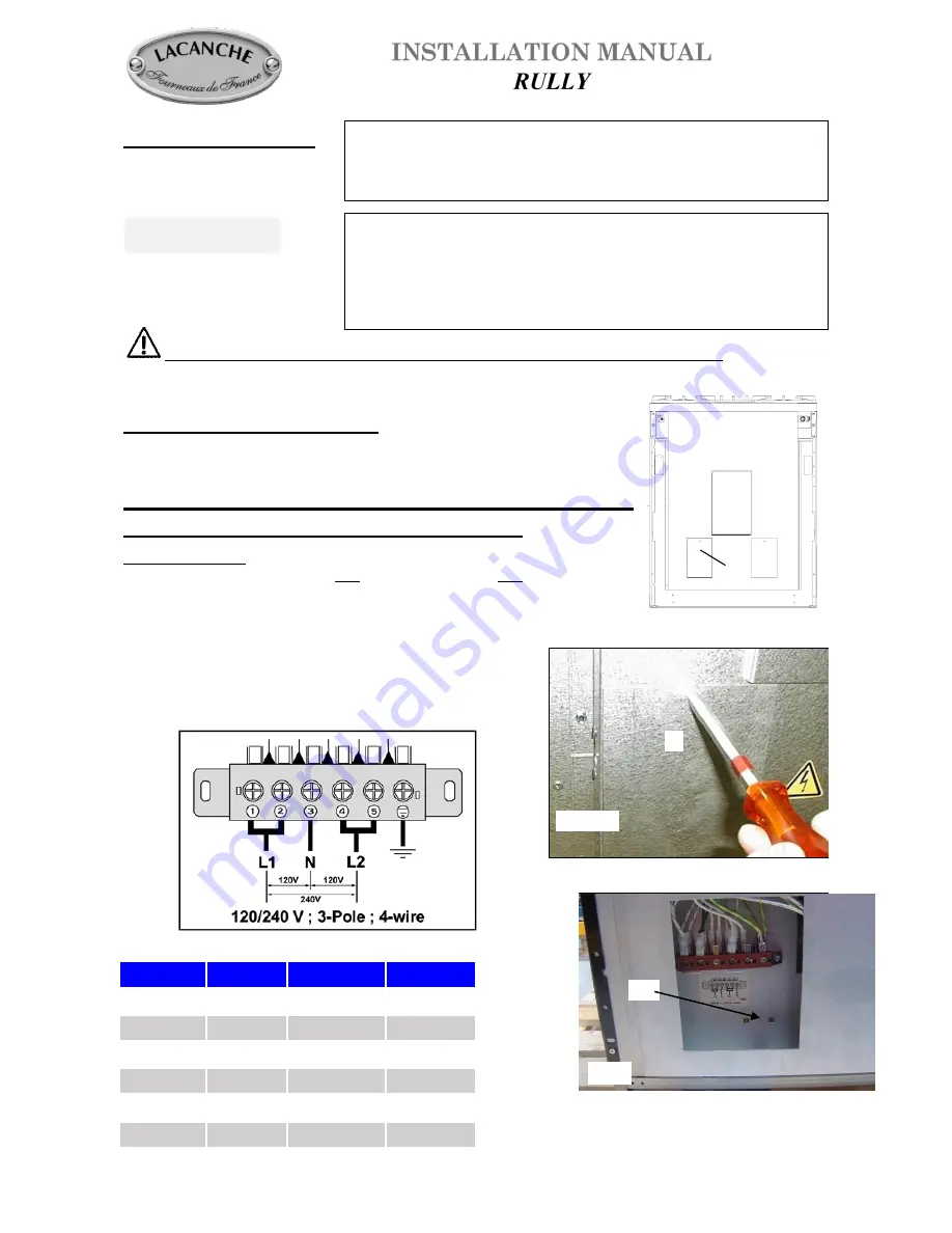
Secure the cable by means of cable clamp


(not provided), item 

(Figure 25). 

Refit access door 


Power Specifications for Rully Ranges 

RULLY  

Voltage (V)  Amperage (A)  Wattage (W)  

ULG732E  

120 / 240  

24.2  

5802  

ULG742E  

120 / 240  

24.2  

5802  

ULG732CT  

120 / 240  

23.2  

5552  

ULG742CT  

120 / 240  

23.2  

5552  

ULCF732E  

120 / 240  

24.2  

5802  

ULCF732CT   120 / 240  

23.2  

5552  


THE  APPLIANCE  WHEN  INSTALLED,  MUST  BE 
ELECTRICALLY  GROUNDED  IN  ACCORDANCE 
WITH THE LOCAL CODES OR The National Electrical 
Code, ANSI/NFPA 70-1996 or latest edition


ALL  WORK  ON  OR  REPAIR  OF  AN  APPLIANCE 
MUST  BE  CARRIED  OUT  BY  A  QUALIFIED 
INSTALLER. 

IMPORTANT


Fig 22 

Fig. 24 


Fig. 25 

Summary of Contents for RULLY

Page 1: ...ully INSTALLATION MANUAL Appliances must be installed in a workmanlike manner in accordance with the instructions in this manual and locally applicable regulations This manual will be handed over to t...

Page 2: ...Page 2 of 17 US...

Page 3: ...acent base cabinet countertop surface Min clearances to combustibles 0 0 mm from rear with spacer installed 0 0 mm from sides below countertop surface height 2 51 mm from sides above countertop surfac...

Page 4: ...time of the order the appliance will be built to use the specified gas type No further work is required by the installer Fig 3 B IMPORTANT Manual shut off valve should be installed in an accessible lo...

Page 5: ...the hob to gain access to the pressure regulator remove the top Convertible Regulator The reversible cap is labeled either LP or NAT and is easily recognized by the raised center screw slot for natura...

Page 6: ...changed the sealing ring should be changed as well see gas circuit diagram Adjustment of primary air Refit the burner bodies and burner caps in their respective recesses adjust the air ring E of the...

Page 7: ...oking surface When refitting the cooking surface it is vital to tighten fastening screws figures 4 5 and 6 Failure to do so can cause distortion of the cooking surface OVEN BURNERS Disassembling of th...

Page 8: ...embly Unscrew pilot injector Replace new injector Table 5 screw in completely until injector bottoms out Replace cap screw Gas pilot LP 65 103032 Gas pilot NG 65 103031 Table 5 GAS Pressure Oven Pilot...

Page 9: ...utral use a 4 wire power supply cord or pigtail kit Cord must be agency approved for use with household ranges Remove access door O P Figure 22 23 Connect to terminal block in accordance with figure 2...

Page 10: ...lied with the appliance Screw the wall spacer to the range according to figure 26 with the thumbscrews and hardware provided Then move the range backwards into position This spacer is reversible to pr...

Page 11: ...e along the seam that the bracket can be freely inserted Figure 2 Mounting screws are not provided This bracket is designed to be mounted to a load bearing support such as a wall stud This anti tip de...

Page 12: ...mple SILICAL GEL BARBAHL Caution Any excess grease should be removed Reverse operation 3 to 1 in that order to put valve and knob back on SAFETY OVERLIMIT THERMOSTAT This purely mechanical switch gove...

Page 13: ...14969 Injector Dia 95 65 14970 Injector Dia 105 65 52863 Injector Dia 120 65 14973 Injector Dia 130 65 14974 Injector Dia 140 65 14975 Injector Dia 145 65 27781 Injector Dia 170 65 30546 Brass knob Ga...

Page 14: ...Page 14 of 17 US 65 39895 65 226006 65 080005 65 033018 1 5 kW 65 064007 3 0 kW 65 064007 4 0 kW 65 064007 5 0 kW 65 064007 65 103029 4 screws 65 129101 4 disc 65 30932 65 103033...

Page 15: ...Page 15 of 17 US D tail A D tail B 65 103032 LP 65 103031 NG 65 103029 65 103033 65 103033...

Page 16: ...ation B Top burner electrode 65 226006 S1 Switch 65 103030 120 V 60 Hz N L1 GR S HT N 4 L 5 HT N 4 L 5 GR S HT N 4 L 5 HT N 4 L 5 GR Top burners code A E 5 N D T I C 01 02 03 0O 0T gas grill code 0Y H...

Page 17: ...2 Circular heating element 2650 W 65 211028 M Convection Fan Motor 65 260001 H Red Lamp 65 231004 H1 Orange Lamp 65 231005 L Oven Lamp 65 232003 Mr Microswitch 65 222011 L1 T1 L2 T2 L3 T3 L4 T4 L1 T1...

Reviews: