


LaCie 12big Rack Network
Module Removal & Replacement
User Manual
page 35
5.1. Overview
The LaCie 12big Rack Network Enclosure includes an Enclosure
Services Processor and associated monitoring and control logic to
enable it to diagnose problems within the enclosure’s power, cool-
ing and drive systems.
The sensors for power and cooling conditions are housed within
the Enclosure Management Card, Ops Panel, CPU(s) and DIMM(s).
There is independent monitoring for each unit.
5.2. ESD Precautions
CAUTION:
It is recommended that you fit and check a suitable
anti-static wrist or ankle strap and observe all conventional ESD pre-
cautions when handling LaCie 12big Rack Network plug-in mod-
ules and components. Avoid contact with backplane components
and module connectors, etc.
5.3. Replacing a Module
CAUTION:
Whenever replacing a module NEVER leave an EMPTY
bay in the rear of the enclosure, obtain a replacement before remov-
ing the problem part.
CAUTION:
Upon module replacement, the enclosure top cover
MUST be secured by turning the lock mechanism to the “locked”
position with a screwdriver.
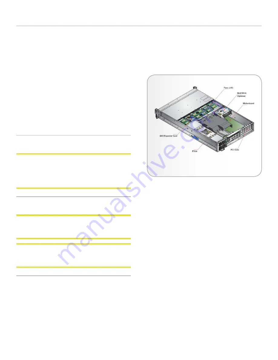
5. Module Replacement
Fig. 19 - ATX Server Component Locations


