background image

4  DESCRIPTION 

20 

TITAN VERSA  Operations and Maintenance Manual  

LACO Technologies 


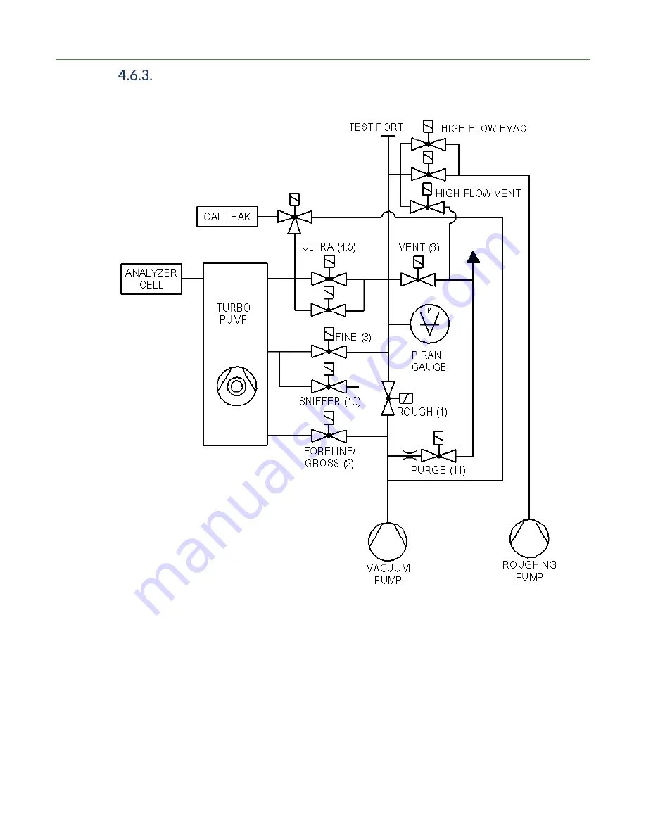
Vacuum Schematic High-Flow Evac and High-Flow Vent with 
Two Pumps 


Summary of Contents for TITAN VERSA C

Page 1: ...TITAN VERSA LEAK DETECTORS OPERATIONS AND MAINTENANCE MANUAL ...

Page 2: ...ch com Manual Name TITAN VERSA Operations and Maintenance Manual Product Group TITAN VERSA Leak Detector Manual Rev Number SMT 07 1037 Rev A2 2020 LACO Technologies Inc No part of this manual may be reprinted translated or duplicated without the expressed written consent of LACO Technologies Inc ...

Page 3: ...nd L Leak Detector 8 Replace Lifting Hardware VERSA T and L 9 Transporting on Mobile Cart 9 3 2 Storage 9 Description 10 4 1 Function 10 4 2 Scope of Delivery 10 4 3 Configurations 12 Feature Locations and Dimensions 13 4 4 Technical Data 16 4 5 TITAN VERSA Part Number Matrix 17 4 6 VacuumDiagrams 18 Vacuum Schematic Main Version 18 VacuumSchematic High Flow Evac and High Flow Vent with One Pump 1...

Page 4: ...tes for Use 42 6 2 Power On Process 42 6 3 Power Off Process 44 6 4 General Use Guidelines 45 Calibration 45 Vacuum Method Leak Testing 51 Sniff Method Leak Testing 52 Gas Charging Process 53 6 5 User Interface Features 54 Touchscreen Display and Buttons 54 Option Button 55 Screen Type Navigation 56 Touchscreen Layout 56 Status Icons 57 Volume Settings 58 User Access Levels 59 Screen Menu Structur...

Page 5: ...100 Manual Control 101 Event History 102 Detector Info 104 Turbo Pump 105 Pirani Calibration 105 Parameters 108 6 11 Advanced Settings 110 Cell Info 111 Advanced Settings 111 Method Correction 112 Cell Tuning 112 Terminal Testing 113 6 12 Factory Default Settings 114 Troubleshooting 117 7 1 Warning and Error Messages 117 Maintenance and Service 122 8 1 Maintenance Cautions and Requirements 122 8 2...

Page 6: ...enance 137 Recalibration 137 Replacement 138 8 13 Valve Block 139 Vacuum Inlet Screens 139 Exhaust Vent Filter 140 Purge Valve Restrictor Filter 140 Valves 141 Pirani Vacuum Gauge Sensor 142 8 14 High Flow Valves 143 Valve Cleaning 143 Valve Replacement 143 8 15 Turbo Pump 144 ReplacetheOilWickin SplitFlow 50 144 Replace SplitFlow 50 for Bearing Change 147 8 16 VERSA T Wet Pump Maintenance 147 Che...

Page 7: ...Quick Method 158 Oil Change Traditional Method 160 Oil Mist Eliminator Maintenance 160 Pump Repair Options 161 Other Pump Parts 161 8 19 VERSA L Dry Pump Maintenance 161 Removing the ISP 90 Pump 161 Pump Maintenance and Repair Option 162 Other Pump Parts 164 Accessories 165 9 1 TITAN VERSA Accessories 165 Appendix 168 10 1 Reference Information 168 Leak Rate Conversions 168 Pressure Conversions 16...

Page 8: ...s Summary 37 Accessory Pin Functions 38 Accessory List Connections and Reference 38 Calibration Types per Mode and Mass 45 Control Unit Buttons 54 Option Button Selections 56 Basic Screen Type Navigation 56 Status Icon Summary 57 User Access Level Summary 59 Screen Menu Structure 60 Test Screen Options 62 Test Screen Added Functions Summary 62 Settings Menu Structure 65 Vacuum Test Mode Summary 68...

Page 9: ... Components 137 TITAN VERSA Valve Block Parts 139 TITAN VERSA Pirani Gauge Components 142 TITAN VERSA High Flow Valve Components 143 TITAN VERSA Turbo Pump Parts 144 Tower Wet Pump Repair Options 152 VERSA T Pump Parts 152 Tower Dry Pump MSV 030 Repair Options 154 VERSA TD Pump Parts 154 Horizontal Wet Pump Repair Options 161 VERSA L Pump Parts 161 Horizontal Dry Pump ISP 90 Repair Options 162 VER...

Page 10: ......

Page 11: ...his operating manual applies to the current state of the products development To access previous manual versions contact LACO Technologies Table 1 below outlines all applicable documents referenced in this manual All manuals are provided on the USB storage drive included with shipment This manual the TITAN VERSA Quick Start User Guide and the TITAN VERSA Communication Interface User Manual are ava...

Page 12: ...ng message Warnings DANGER Imminent threat of danger resulting in death or severe injuries Dangerous situation potentially resulting in death or severe injuries WARNING Dangerous situation resulting in major injuries Dangerous situation resulting in damage to property or the environment CAUTION Dangerous situation resulting in minor injuries NOTICE Dangerous situation resulting in damage to proper...

Page 13: ...nces Do not suck up dusts or solids NOTICE Improper use will cause all claims for liabilities and warranties to be forfeited Improper use is defined as usage for purposes deviating from the intended uses stated above especially Pumping harsh chemical corrosive flammable reactive toxic or explosive fluids Pumping of liquids Pumping of condensing vapors Pumping dust or solids particles Operation in ...

Page 14: ...vice Qualified service technicians must receive training on the device Allow personnel in training to work with and on the device only under the supervision of trained qualified service technicians Before starting work ensure authorized personnel read and understand the operating instructions and all other applicable documents see Reference Documents especially the information regarding safety mai...

Page 15: ... Before connecting the device to the power supply make sure that the supply voltage specified on the device is the same as the local power supply Dangers from liquids and chemical substances Liquids and chemical substances can damage the device Adhere to restrictions of use see Technical Data Do not suck up liquids with the device Never contact toxic caustic microbiological explosive radioactive o...

Page 16: ...tional 20 minutes Only then will the pump oil be free of condensed vapors WARNING Overpressure Overpressure may destroy the vacuum pump the vacuum system and the gaskets Do not create an overpressure with the device Only use the device for leak testing WARNING Halogens in gas If gas whose molecules contain halogen is measured with the device the cathode layer of the ion source may be attacked This...

Page 17: ...ct sunlight NOTICE TITAN VERSA Wet Pump Version Risk of oil damage during transport Transport the device upright and level Otherwise pump oil may flow out of the exhaust line and can damage the device Do not change device orientation from upright and level for transporting To avoid risk use the plug supplied with the device to close the exhaust line Remove the plug to be operational again after th...

Page 18: ...tart Guide TITAN VERSA Operations and Maintenance Manual Tools and Replacements Box Lifting kit bag and replacement hardware Remove VERSA C Leak Detector The VERSA C Compact model does not include a lifting strap described in the sections below Remove the unit from packaging using the following process 1 Remove foam panels from sides of leak detector 2 Remove protective plastic from leak detector ...

Page 19: ...n lifting kit bag 3 Locate two M8 flanged screws inside of lifting kit bag and insert where lifting bolts were located Transporting on Mobile Cart Never move unit while the detector is on Unit is safe to move once the unit has been off for five minutes and turbo pump has safely spun down Store the device under the following conditions Ambient temperature A cool dry place Ensure the inlet test port...

Page 20: ...hamber Toaccomplish this the TITAN VERSA is connected to a vacuum chamber The device measures the overall leakage rate of the test object This type of leak test is often referred to as Inside Out testing The device has three sensitivity levels for vacuum method GROSS FINE and ULTRA Depending on the pressure in the inlet flange and the user settings the TITAN VERSA automatically selects the most se...

Page 21: ...erally needed for leak testing The provided USB drive contains files located per the file structure summarized below USB Drive Folder Structure Root Folder Sub Folder Manuals TITAN VERSA Accessories Pumps Manuals Reference Brochures Catalog Certification Technical Reference Application Notes Drawings PDF STP Video Operation Maintenance ...

Page 22: ...A are summarized in Table 4 below VERSA Body Style Configurations Body Style Configuration Height mm in Width mm in Depth mm in Pump Type VERSA C Compact 403 15 8 562 22 1 323 12 7 None customer provides VERSA L Horizontal 403 15 8 562 22 1 497 19 6 Wet or Dry VERSA T Tower 607 23 9 562 22 1 323 12 7 Wet or Dry VERSA C VERSA T VERSA L ...

Page 23: ...ns 4 3 1 1 VERSA C Features and Dimensions ID Feature 1 Vacuum test port 2 Sniff test port 3 USB Port 4 Display and Cycle Start button 5 Product label 6 Power entry module 7 Multi Use ports Area 1 9 Electrical Interface 12 Fan inlet with filter 14 External pump port 15 Secondary external pump port for High Flow ...

Page 24: ...res ID Feature 1 Vacuum test port 2 Sniff test port 3 USB Port 4 Display and Cycle Start button 5 Product label 6 Power entry module 7 Multi Use ports Area 1 8 Multi Use ports Area 2 9 Electrical Interface 10 Oil sight glass 11 Oil fill area 12 Fan inlet with filter 13 Pump fan with filter 15 Secondary external pump port for High Flow ...

Page 25: ...imensions VERSA L Features ID Feature 1 Vacuum test port 2 Sniff test port 3 USB port 4 Display and Cycle Start button 5 Product label 6 Power entry module 7 Multi Use ports Area 1 8 Multi Use ports Area 2 9 Electrical interface 10 Oil sight glass 11 Oil fill area 12 Fan inlet with filter 13 Pump fan with filter ...

Page 26: ...ar L sec 5 x 10 9 Vacuum test modes with max inlet test pressure Gross 25 mbar Fine 5 mbar Ultra 0 5 mbar Protection category IP 20 Inlet flange DN 25 ISO KF Filament 2 iridium yttriated Turbo pump flow SplitFlow 50 53 L s N2 Operating temperature range Vacuum C 0 45 0 45 0 45 0 45 0 45 Operating temperature range sniff C 0 45 0 40 0 40 0 45 0 45 Noise level dB A N A 58 56 57 58 Electrical supply ...

Page 27: ...RSA Operations and Maintenance Manual 17 Environmental Conditions Environmental Conditions Storage temperature 20 C to 55 C Maximum humidity of air 85 without condensing Maximum magnetic field 3 mT Maximum altitude above sea level 2000 m ASL ...

Page 28: ...4 DESCRIPTION 18 TITAN VERSA Operations and Maintenance Manual LACO Technologies Vacuum Schematic Main Version ...

Page 29: ...4 DESCRIPTION LACO Technologies TITAN VERSA Operations and Maintenance Manual 19 Vacuum Schematic High Flow Evac and High Flow Vent with One Pump ...

Page 30: ...4 DESCRIPTION 20 TITAN VERSA Operations and Maintenance Manual LACO Technologies Vacuum Schematic High Flow Evac and High Flow Vent with Two Pumps ...

Page 31: ...ating the device can lead to personal injury from electric shock and to material damage from short circuits Only operate the TITAN VERSA in a dry environment Operate the TITAN VERSA away from sources of liquid and moisture Positionthedevicesothatyoucanalwaysreachthemainsplugand disconnect thedevicefromthemainsbyunpluggingthemainsplug NOTICE Material damage due to overheating The device heats up du...

Page 32: ...or will be damaged Remove the KF 25 blank off flange on vacuum test port inlet and save it for reuse during storage or transport 5 2 1 1 Inlet Port Filtration Each TITAN VERSA unit is proved with two mesh screens filters as outlined in the picture below These filters should be cleaned yearly or more frequently in dirty applications Figure 1 Inlet Mesh Screen Filters Items 8 and 9 The sintered bron...

Page 33: ...h good vacuum practice Use pipe with a diameter equal to the diameter of the detector s inlet The pipes should be as short as possible and completely sealed Do not use plastic hoses such as compressed air pipes Check that the connected part installation is impermeable to tracer gas Test only clean dry parts or installations with no trace of water vapor paint detergent or rinsing products Test that...

Page 34: ...RSA C Compact configuration does not include a primary vacuum pump The user must supply the following items in this configuration Primary pump meeting the following specifications Ultimate pressure below 3 mbar Pumping speed greater than 2 m3 h Vacuum hose with KF 25 end connection Power connection to external primary pump ...

Page 35: ...able 9 and 10 below outline the required connections for various High Flow Evac conditions for the different TITAN VERSA models High Flow Evac Internal Configurations One Pump High Flow Evac Two Pump High Flow Evac VERSA C Compact VERSA T Tower This version not available VERSA L Horizontal This version not available ...

Page 36: ...RSA Operations and Maintenance Manual LACO Technologies VERSA High Flow Evac External Configurations One Pump High Flow Evac Two Pump High Flow Evac VERSA C Compact VERSA T Tower This version not available Small pump Large pump ...

Page 37: ... to lower KF 25 port 5 2 3 2 VERSA T TOWER High Flow Evac The VERSA T model requires an external pump Connect the external pump to the KF 25 port on the back cover Ensure all connections are leak tight 5 2 3 3 VERSA L HORIZONTAL High Flow Evac The VERSA L model uses the internal pump only No external connections are needed Sniffer Port 1 Connect the sniffer probe into the sniff port 2 Connect the ...

Page 38: ... VERSA C Vent Blank N A N A N A VERSA T Wet Vent Pump exhaust Oil drain Spare Remove Back Cover VERSA T Dry Vent Spare Pump exhaust Spare N A VERSA L Wet Vent Spare Oil drain Pump exhaust Hole in top rear cover VERSA L Dry Vent Spare Pump exhaust Spare N A TITAN VERSA Multi Use Port Details Port Specification Picture Vacuum vent 12 mm tube Pump exhaust wet pump 12 mm tube 1 3 4 2 2 1 4 3 ...

Page 39: ... port vents the vacuum test line back to atmosphere pressure after a test is completed It is always labeled with a VENT label If the testing area air concentration is free from tracer gases this connection can typically be left open and the test volume will be vented with ambient air Alternatively users can install a tubing section to ensure vent air is coming from a cleaner area Ensure tube secti...

Page 40: ...be connection If the VERSA is operated in poorly ventilated spaces an exhaust gas line is recommended An exhaust gas line is not included in the scope of delivery It is the duty of the owner to provide an exhaust gas line and to ensure the discharge of exhaust gases Do not connect long tube sections to this port this can adversely affect pump performance Use short large diameter tubing sections se...

Page 41: ... port is provided In the TITAN VERSA Tools and Spares Kit there is a drain line connection assembly P N TV118495 that can be used to easily drain the vacuum pump oil See the following oil change sections for more details VERSA T oil drain VERSA L oil drain 5 2 5 4 Vacuum Pump Oil Fill See the following sections for details on oil change and oil fill VERSA T oil fill VERSA L oil fill ...

Page 42: ...age specified on the TITAN VERSA product label matches the supply voltage available on site Verify the available power source matches product voltage 2 Connectthedevicetotheelectricpowersupplyusingthesupplied power cable Electrical interface connections are located on the right side of all TITAN VERSA configurations Table 13 summarizes all the interfaces connection specifications parts and accesso...

Page 43: ... outputs M12 5 pin female TV115893 module TV5839 1 m cable TV5840 3 m cable TV5841 5 m cable 9 Local I O M12 8 pin female TV5944 screw terminal connector TV5943 5 m cable TV118379 Start Stop box USB Port A USB host port is provided next the sniffer port on the front of the unit The user shall only plug in a USB drive to the port No other USB devices are supported The USB port is provided for the f...

Page 44: ...ic 6 Analog Output 3 Analog Output 0 10 VDC Default to Leak Rate Exponent 7 Selected Test Mode Reached Digital Output Open Collector Connect 5V pin and output pin 8 Leak Rate greater than Reject Point Digital Output Open Collector Connect 5V pin and output pin Figure 3 Local I O Pin Locations The local I O is provided primarily for the analog output features See Local I O operation section for det...

Page 45: ...ess button to start test cycle In Mode Press button to end cycle Figure 5 Start Stop Box TV118379 Serial Port The serial communication serial port female DB 9 has both RS232 and RS485 protocols available Table 15 below outlines the pinout for the DB 9 connector The following baud rates are available in Communication settings 9600 19 200 57 600 and 115 2000 These can be set at Menu System Communica...

Page 46: ...computer does not have DB9 serial port use a USB to serial adapter P N LMSA0360 Serial DB9 Pinout PIN Function 1 RS485 A 2 RS232 TxD 3 RS232 RxD 4 NC 5 Gnd RS232 6 NC 7 NC 8 NC 9 RS485 B Ethernet Port The RJ45 Ethernet port is currently not functional Functionality will be added in a future software release Barcode Reader To access the barcode reader features the LACO barcode reader P N TV118566 m...

Page 47: ...Remote I O Functions Summary I O Function Total Detail Electrical Spec Digital Input 8 8 Bi directional PNP or NPN 15 30 VDC On Voltage Optical Isolation 10 msec response Digital Output 8 6 Relay 2 PNP transistor Relay DC or AC load Transistor 24 VDC 250 mA max Analog Output 2 Voltage 0 10 VDC or Current 4 20 mA 12 bit A D 0 2 of full scale Current max load 500 Ohm Voltage max load 1000 Ohm The TI...

Page 48: ...on 1 BRN Normally closed connection 24 VDC in off position 3 BLU 0 VDC 4 BLK Normally open connection Figure 6 Accessory Pin Locations Table 18 below contains a list of current accessories and how to connect them After connecting an accessory go to Menu System Accessories to configure the accessory Accessory List Connections and Reference Accessory Connection Reference High Flow Evac Always Accs 1...

Page 49: ... screen accessory allows users to mount a remote screen when the main screen is not accessible Connect the M8 cable from remote screen port to male M8 port on the remote screen Configure remote screen to Menu System Accessories See the Remote Screen Manual SMT 07 1041 for more information on the screen and various mounting options Figure 8 Remote Wired Screen ...

Page 50: ... To connect the Wireless Handheld Pendant 1 Power on the leak detector 2 Connect the serial to Bluetooth adapter into wireless remote male DB9 port and power on the adapter Note the MAC address 3 Power on the remote 4 From the list select the correct MAC address Unit is connected wirelessly and directs to home page Refer to the RC10 Manual P N 124628 for more information Figure 9 Wireless Handheld...

Page 51: ... Expert advice on cost efficient and quick solutions to your service needs Available rentals when a TITAN VERSA is sent for repair or preventive maintenance On site and LACO facility trainings for TITAN VERSA and many other LACO products Original parts on all repairs and preventive maintenance For more information on our services see LACO Service Solutions or contact LACO Technologies directly Pho...

Page 52: ...nal primary pump must be connected and powered up before the detector is switched on Each time before powering on the TITAN VERSA 1 Become familiar with the safety instructions see 2 Safety 3 Check that all the connections are correct see Installation 4 Ensure that leak detector will be operating in an environment free of tracer gas 5 Check the electrical network is properly attached to the connec...

Page 53: ...500 Hz The startup time for the turbo pump ranges from two to five minutes After the turbo pump reaches full speed the Mass Spectrometer Mass Spec will verify filament function and proper emission If the leak detector has not been used for 15 days the unit will undergo a storage delay setup 5 After startup is complete the test screen appears and the leak detector status will read Standby NOTICE Al...

Page 54: ... using stored energy from the turbo pump controller Note that during this state only the control system is power on the vacuum pumps and detector and powered off During shutdown the purge valve valve 11 opens to vent the pump foreline This feature prevents oil migration in the cell block in the case of anti suck back valve failure on a wet pump NOTICE Safe to move detector Only after the leak dete...

Page 55: ...tion Refer to Calibration Settings NOTICE Leak Standard Calibration Frequency LACO recommends the internal calibrated leak standard be calibrated at least every two years Sniff calibrated leaks and higher leak rate external leaks 1 0 e 6 mbar L sec should be calibrated yearly or more frequently if the depletion rates are large The TITAN VERSA Leak Detector offers both internal and external calibra...

Page 56: ...ll proceed through an automated calibration sequence The user can press the Stop Cal button if they wish to abort the calibration The calibration sequence has the following main states peak find peak measure and background check During a calibration the acceleration voltage and the calibration factor are changed During background check the detector verifies acceptable background readings This back...

Page 57: ...s the calibration reading is within 20 of adjusted leak rate value 4 If the unit fails a Cal Check the user will be notified via a warning See Calibration History for results on both Cal Checks and calibration cycles 6 4 1 3 External Calibration Vacuum Method NOTICE External Vacuum Calibration Availability The external vacuum calibration method is available for all test gas masses NOTICE External ...

Page 58: ...t with the calibrated valve open 3 Press the Calibrate icon 4 Verify the Calibrate option and press Start 5 Verify External Calibrated leak setting configurations Press Continue to start the calibration or Edit to change the calibrated leak valve settings 6 Confirm calibrated leak valve is open 7 Calibration proceeds through peak find and peak measure 8 Dialog prompts user to close calibrated leak...

Page 59: ...brated leak settings are entered External leaks require an estimated calibrated leak temperature LACO manufactured leak standards are very temperature independent so entering an average temperature of around 25 C will work for most applications Sniff calibrations do not require a valve on the calibrated leaks standard Contact LACO for the industry s largest selection of calibrated leak standard op...

Page 60: ...eak setting configurations Press Continue to start the calibration or Edit to change the calibrated leak valve settings 8 Confirm sniffer probe is connected and leak rate is stable Keep sniffer probe inserted 9 Calibration proceeds through peak find and peak measure 10 Dialog prompts user to remove sniffer probe After probe is removed press Continue ...

Page 61: ...on reviewing calibration results Vacuum Method Leak Testing 6 4 2 1 Outside In Leak Testing In this method the test object is evacuated direct connection to vacuum inlet test port KF 25 and the user sprays helium to verify test leak integrity This method allows for leak location If test objects are small enough a plastic bag can be placed over the test object and helium sprayed into bag This metho...

Page 62: ...er The schematic below shows the test part being filled inside the vacuum chamber This method is ideal for a high sensitivity global leak test The following accessories can aid in testing using this method See Accessories for more details Gas Charge Manifold LHREG 01 0 100 psi bottle regulator for helium gases P N CGA580 Sniff Method Leak Testing Sniff leak testing is an atmospheric leak test meth...

Page 63: ...the ambient air is contaminated with helium a large fan can be used to exhaust the test area and provide clean air When sniffing a part with multiple potential leak locations always begin sniffing near the bottom of the part and work towards the top It may be necessary to repair leaks that are found before proceeding Helium escaping from the part will rise and can give a misleading leak location G...

Page 64: ... a color touchscreen display Start Stop cycle button and a user programmable option button for the main user interface items Table 20 below describes how each device is used to control the detector Control Unit Buttons ID Name Function 1 Touchscreen Display Press on the relevant area to perform the needed functions The settings for many functions can be accessed quickly by pushing down on an icon ...

Page 65: ...button for a commonly used feature The selection of the Option button is located to the right of the physical button on the touchscreen To edit the current configuration press and hold the screen area for one second The following screen appears The user can toggle through the various options as outlined in Table 21 The Option button can also be edited from Settings System Display ...

Page 66: ...ts while the settings screen allow the user to change device settings In the upper left of the touchscreen there are two main icons that allow for access to either a settings screen or test screen Basic Screen Type Navigation Screen Family Icon Description Test Press Home icon to get to test screens Settings Press Settings icon to show settings main menu Touchscreen Layout The common areas of the ...

Page 67: ...n Icon Description Login Level Operator Login Not set up by default If configured the base user has very limited access to change parameters Technician Login Access all features except advanced Advanced Login Login for service centers or advanced users Method Mode Mass Dynamic Icon indicate main unit settings Main Symbol Vacuum or Sniff Subscript Test Mode G Gross test mode F Fine test mode U Ultr...

Page 68: ...gs Off Low Med High Volume Settings The TITAN VERSA has an audio output signal that correlates with the current leak rate vs the reject limit The larger to difference between current leak rate and reject limit the higher the pitch If the audio is on and the leak rate is lower than the reject limit than the audio signal will be off Audio signals are ideal for sniff leak testing To adjust the audio ...

Page 69: ...tings Operator Level To protect settings from accidental changes and restrict operators to start and stop cycles and calibrations only the user must enable the Operator level see Parameters section To set up the Operator level the user must first enter a new technician password Once enabled the system default boots to the Operator level This level is disabled by pressing the Login level icon and e...

Page 70: ...n Calibrated Leak Calibration Start Calibration History Cal History Detail System Mass Spec Units Display Accessories Communication Terminal Testing Remote I O Digital Input Digital Output Analog Input Local I O Maintenance Maintenance Tasks Maint Task Details Counters Manual Control Event History Event History Detail Detector Info Software Versions Turbo Pump Info Parameters Software Update Piran...

Page 71: ...reen To take a screenshot 1 Insert USB drive into USB port 2 On the desired screenshot screen the user will press in the bottom right area for two seconds See the area indicated by a red square in the screen shot below 3 The following dialog appears Press the OK button to capture the current screen Note that the HMI will become unresponsive for about 20 seconds after the screenshot event occurs ...

Page 72: ...h Test Graph Large 2D leak rate plot with many options settings Test Screen Quick Access Features Table 27 outlines five commonly used test features in the test screens These features may be accessed through either the Test screens or Settings menu Test Screen Added Functions Summary Function Icon Description Calibration Press the Cal icon to perform either calibration or calibration check process...

Page 73: ...scretion Cycle Combo method While in cycle in log all data per log interval and log single summary row at end of cycle Test ID Test ID functions allow user to attach Test ID attributes to a specific test Test ID Function Test ID functions allow user to attach Test ID attributes to a specific leak test To access the Test ID settings the user must select the Test ID icon from the test screen Enter d...

Page 74: ...ust first select the Test ID icon from the test screen and then select the Setup option The screen below appears Test ID Fields The user can define up to five user defined Test ID parameters These parameters are typically used in data logging Examples include Operator Part Number Serial Number Lot number Test Description ...

Page 75: ...s defined as Required and the field data is empty the Test ID screen will automatically appear on cycle start command Clear After If a field is defined as Clear After the field contents will be deleted when a full test is completed This field is helpful for unique field options such as serial number Settings Main Menu To access the main Settings menu from the test screens press the menu icon three...

Page 76: ...6 OPERATION 66 TITAN VERSA Operations and Maintenance Manual LACO Technologies The test settings section has the following sub menus Test Settings Reject Levels Vent AutoTest Zero Data Log ...

Page 77: ...6 OPERATION LACO Technologies TITAN VERSA Operations and Maintenance Manual 67 Method Settings ...

Page 78: ...In most applications Ultra mode should be used as the final test mode Note When in sniff mode this parameter will be hidden Vacuum Test Mode Summary Vacuum Test Mode Maximum Pressure mbar Helium Pumping Speed L s Where used Gross 25 Depends on Primary pump speed Larger leak rates or applications where deeper vacuum levels are difficult to achieve Fine 5 1 0 Medium leak rate signal response and sen...

Page 79: ...spray helium to help locate large leaks Once the leak is fixed the pressure can go below 25 mbar and the test will go into full cycle Reject Limits Reject Limits Reject limits can be entered for either vacuum or sniff test methods Rejects limit are used throughout the unit in the following ways On Test screens indicating Pass Fail conditions green indicates Pass red indicates Fail Reject limits de...

Page 80: ...cate clogged sniffer probe Inspect sniffer probe when this occurs Gross Leak Setpoint The Gross Leak Setpoint parameter prevents excess tracer gas from contaminating the detector When this setting is enabled and the leak rate exceeds the gross leak setpoint the test cycle stops automatically and returns to standby mode It is recommended to set the gross leak setpoint to a maximum of 4 decades abov...

Page 81: ...ar in this condition Method Auto Vent In Auto Vent mode the system automatically vents the test volume at the end of the cycle per the vent settings timers see Vent Timer below Vent Delay Vent Delays of 0 1 or 2 seconds are allowed after cycle ends before the vent valve opens Vent Delays can occur in both Manual and Auto Vent modes Vent Timer The vent timer can be enabled or disabled If disabled t...

Page 82: ...6 OPERATION 72 TITAN VERSA Operations and Maintenance Manual LACO Technologies AutoTest Settings ...

Page 83: ...m the test on the test screen The text Last Result is displayed See image below for example Zero Settings NOTICE Use of Zero function The use of the Zero function is recommended when the background signal is stable and significant The Zero function can assist the operator in finding smaller leak rate variations Zero function features include Recording signal background when the zero function is ac...

Page 84: ...ress enables zero mode Manual Zero Start Stop To start or stop the Manual Zero method the button press can be either a quick press or long press 2 seconds Zero Auto Trigger The Zero Auto Trigger can be set to either the threshold leak rate or timer Zero Threshold To set Zero Threshold enter the leak rate at which you need Zero function to start Zero Timer Enter the desired Zero time at which the Z...

Page 85: ...st successful calibration This function works both in Standby and Test modes This feature is enabled by default and can be used to measure a leak rate two decades lower than the detector s background Data Log Settings NOTICE USB drive For data logging features to function a USB drive must be inserted in the USB port A USB is provided in shipment in documentation packet Spare drives can be ordered ...

Page 86: ...or users requiring traceability for their leak test application To enable the Test Summary Method 4 Select Test Summary from the log method and press the Data Log Enable button 5 When in a test cycle is in process the Data Log icon will flash with a T symbol Additionally the bottom the test screen will read Data Logging Active 6 The data is logged at the end of the test cycle Test Summary Field De...

Page 87: ...ot stopped after 1 hour it will be automatically shut off After a stream data log concludes a CSV file appears on the USB drive The file nomenclature is TestData Date Time csv For example Stream data is ideal for in depth analysis of leak testing data Stream files contain pre filled headers followed by the generated file data The headers include the following fields Date Time Test Method Vac Mode ...

Page 88: ... described above Enter any test ID data that is desired before running the leak test see Test ID Entered data will be logged This data log method is ideal for customer requiring traceability for their leak test application Graph Settings On the Test Graph screen the user can select the desired graphing options per the parameters below To edit graph settings press the Setup button on the graph scre...

Page 89: ...ing Reference Select either Reject Limit or Current Value for the scaling reference This setting only applies to Automatic Scaling Low Decade Select the low decade range between 12 and 5 Decade Range User can display from one to six decades in graph Overall Graph Range Select options of 1 minute 2 minutes 4 minutes or 30 seconds Logarithmic Select to graph values to log scale default graph logs in...

Page 90: ...6 OPERATION 80 TITAN VERSA Operations and Maintenance Manual LACO Technologies The calibration settings menu has the following sub menus Calibrated Leak Standard Calibration Start Calibration History ...

Page 91: ...bration Method per Mode and Mass Calibration Method Mass Test Mode Internal Helium 4 Vacuum External Vacuum Sniff Helium 3 Vacuum Sniff Hydrogen Vacuum Sniff Internal calibration cycles are fully automated using the internal leak standard For external calibrations the user must follow the on screen prompts to introduce and remove the leak standard at certain time See Section 6 4 1 for more informa...

Page 92: ...MMYYYY format Cal Temp Enter the leak standard calibration temperature in Celsius Temp Coefficient Enter the temperature coefficient in 0 1 precision Depletion Rate Enter the depletion rate Round to nearest whole percentage number Current Temperature Enter the estimated current leak standard temperature in degrees Celsius only for External leaks Calibration Start Cal Start Method There are three o...

Page 93: ...urs or cycles have been reached Cal Check Auto Hours Enter desired hours before performing cal check Cal Check Auto Cycle Enter desired cycles before performing cal check NOTICE Use caution when using the Machine factors as they can give incorrect readings if used improperly The factors will adjust all leak test readings Only use machine factors when external calibrations have been used to verify ...

Page 94: ...iew of the last 20 calibrations or cal checks Six calibrations can be viewed per screen use the scroll button to toggle through the history Select the desired the event to review and the following screen will appear where the user can review the calibration history In a calibration both the cal factor and acceleration voltage Vacc are adjusted ...

Page 95: ...ERATION LACO Technologies TITAN VERSA Operations and Maintenance Manual 85 The calibration settings section has the following sub menus Mass Spec Units Accessories Communication Local I O Remote I O Display ...

Page 96: ...dard of the same gas species Active Filament The detector has two filaments The user can switch to filament 2 when filament 1 has higher cal factors 20 When the filament is changed the user must recalibrate the system Filament On Off The filament should only be turned off in cases of required maintenance or troubleshooting Filament Status This parameter indicates the relative life of the filament ...

Page 97: ...ot be selected but are dependent on the leak unit selected Leak Rate Unit Options Leak Rate Units Pressure Units mbar L s mbar Pa m3 s Pa Torr L s Torr Atm cc s mbar ppm mbar sccm mbar sccs mbar mTorr L s mTorr Date and Time Press the Date and Time box and the screen below appears Set the desired date and time and press the Back button to save Date format MMDDYY Time Format HHMMSS in 24 hour milit...

Page 98: ...s Audio Settings The audio setting is turned off by default Select toggle to turn on Audio levels range from 0 off to 9 loudest Audio levels can also be adjusted by pressing the audio status icons upper right Additionally the option button can be programmed to mute audio signal ...

Page 99: ...n authorized accessory is connected configure the settings per the following available accessories High Flow Evac High Flow Vent and Pass Fail light If no accessory is configured select the None option When the High Flow Evac valve is configured the user must select from the options summarized in the following table ...

Page 100: ...ondition is referred to split flow User should use Machine Factor adjustment Remote Screen Enter if the Remote Screen accessory is attached Communication Settings Serial Baud Rate Enter the desired baud rate for both the RS232 and RS485 communication methods Available baud rates are 9600 default 19200 57600 and 115200 All communication adheres to the following additional serial settings Bits 8 Par...

Page 101: ...ption type buttons to configure the required I O Below is a summary of the default I O configurations Remote I O Default Options ID Digital Inputs Digital Outputs Analog Outputs 0 Start Stop Reject 1 Mantissa 1 Sniff Vac Ready to Start Exponent 2 Internal Cal LD error 3 Zero In final test mode 4 Inlet Vent Calibrate Ack 5 Clear Error Reject 2 6 Int Cal Check Reject 3 7 Go to Ultra mode Calibration...

Page 102: ...put Options Digital Input Comments Start Stop Not in cycle and receive input then start If in cycle and received input then stop cycle Sniff Vac Default is vacuum Internal Cal Set to internal calibration mode then initiate a calibration Zero Toggle Zero function to On Off Inlet Vent Toggle Vent valve Open Closed Clear Reset error or warning message Int Cal Check Set to internal calibration mode th...

Page 103: ...ject 3 Turn on when leak rate is below user defined limit level 3 Ready to Start Status is standby In test Status is in cycle In final test mode Mode is in test mode as set LD error Leak detector has reported an error Calibrate ACK Calibration ACK received User must respond LD error or warning Leak detector has reported a warning Calibration Active Calibration in progress Sniff Active Leak Detecto...

Page 104: ...ohm Current Conditions 4 20 mA max load 500 ohms Local I O Three analog outputs can be configured on the Local I O connector per the following options Leak Rate Mantissa Leak Rate Exponent Leak Rate Logarithmic Leak Rate Compound Inlet Pressure Configure the analog outputs referencing the following information For the Exponent and Logarithmic selections the user must also enter the low decade info...

Page 105: ...responds with the leak rate value it increases by 1 V per decade the starting decade corresponds with 0 V Formulas U Voltage measured V on analog output D0 Low decade for 0 V Mantissa 10 U Integer value U Exponent Integer value U D0 Leak rate Mantissa x 10Exponent Example 1 Low decade at 10 12 0 V 1 10 12 D0 12 V 3 91 V Leak rate 10 3 91 3 x 10 3 12 8 13 10 9 V 8 25 V Leak rate 10 8 25 8 x 10 8 12...

Page 106: ...Compound Mantissa x 10Exponent Examples U 3 91 V He Compound 10 x 3 91 3 x 10 3 12 9 10 10 9 U 8 25 V He Compound 10 x 8 25 8 x 10 8 12 2 50 10 4 Inlet Pressure The Inlet Pressure output corresponds with the inlet pressure source Formula U Voltage measured V on analog output Inlet pressure 10 U 5 5 hPa Display ...

Page 107: ...0 min 20 min and 30 minutes By default the screen is set to no dim time Option Button Select the desired Option key function from the table below Option Button Selections Option Function Comments None Zero Only works in Manual zero method Vent Only works in Manual Vent options Data Log Only works from stream method Test Summary and Test Summary and Stream will automatically data log Mute Press but...

Page 108: ...est to furthest Maintenance due dates are determined from the maintenance tasks and intervals table see Maintenance Tasks and Intervals product configuration and when maintenance was last performed When maintenance items are close to being due the maintenance icon wrench on the test screen status icon area will appear orange When items are due the icon will become red ...

Page 109: ...the Reset button and the following dialog will appear Press the OK Button Ignore Maintenance In rare cases the user may need to temporarily ignore a maintenance warning However this is not recommended in usual practice In this case the dialog below appears The maintenance due date will remain the same even if the warning is ignored but the warning will be suppressed ...

Page 110: ...valves should be replaced Turbo Pump Hours Displays current turbo pump hours Reset only with a new or refurbished turbo pump Turbo Maint Hours Turbo pumps should be serviced every 17 200 hours Filament 1 2 Hours Displays the current hours for filaments 1 and 2 When filaments are replaced the hour counters should be reset to 0 Detector hours Display the current total detector hours ...

Page 111: ...view and troubleshoot the leak test process Vacuum schematic view of leak detector User can run a test cycle or calibration to observe valve cycle process Visual indications of valve state system status pressure and leak rates Control of purge valve This is the only valve that can be controlled through the HMI Ability to Start and Stop leak test cycles ...

Page 112: ...d cleanup process runs This process consists of running the detector for one hour while the unit undergoes an automatic continuous cycle and vent process This process can be viewed either from the Test screen or the Manual Control screen and is ideal for applications where the background requires improvement or when new valves are installed on the valve block Event History ...

Page 113: ...ow will appear All faults warnings and events are logged to event history Reviewing these events can aid in troubleshooting Table 40 outlines all available event codes Event Logging Code Description 300 Air inlet 301 Stop Cy He He max 302 Reset count RVP 303 Reset count TMP1 304 Reset count TMP2 305 Reset count TMP3 306 Reset count Fil1 307 Reset count Fil2 308 Reset count cycle 309 Ie increase 31...

Page 114: ...zes key performance data as shown below This information can aid in troubleshooting 6 10 5 1 Software Versions Press the Software button to display the Software versions screen For informational purposes the software revisions the of the following items are summarized HMI Software Supervisory Board Software Mass Spec Software ...

Page 115: ...marizes key pump performance data as shown below This information can aid in troubleshooting Pirani Calibration The Pirani vacuum gauge sensor should be calibrated every six months The calibration process had two main steps Atmosphere reading Deep Vacuum reading take 3 5 minutes to ensure deep vacuum has been reached ...

Page 116: ... inlet vent 3 Verify system is fully vented by removing flange or chamber 4 Wait for Atmospheric reading to stabilize for at least 30 seconds 5 Press the Set Atmosphere Count button 6 Proceed to Deep vacuum section below Deep Vacuum Reading Setting deep vacuum pressure 1 Place KF 25 blank off on vacuum inlet 2 Verify test mode is in Ultra 3 Press Go to Vacuum Button ...

Page 117: ...d Maintenance Manual 107 4 Leak detector will go into test and evacuate for five minutes The text Stabilizing Please wait will show 5 After five minutes press the Set Vacuum Count button and then press the Stop button and the screen will automatically close ...

Page 118: ...ed Operator Level This option allows the user to setup a new user level called Operator Once active most parameter settings will be locked out This setting is ideal for customer applications where users want to restrict parameter access Select the Set Technician Level Password button Set up a four digit password This new password enables the technician user to have access to the all parameters exc...

Page 119: ...ide three files firmware application and key file To perform a software update 1 Place USB drive into PC and copy and paste these files onto a Windows formatted USB drive 2 Place USB drive into USB port on TITAN VERSA 3 Navigate to the following screen Settings Maintenance Parameters and press the Software Update button The screen below appears 4 Press the Start Update button 5 The update will tak...

Page 120: ...be used by qualified technicians and used with extreme caution Careless changes of settings could result in poor performance or device damage The Service settings section has the following sub menus Cell Info Advanced Settings Method Correction Cell Tuning Characterization Terminal testing Serial Ethernet and barcode ...

Page 121: ...nformation can aid in troubleshooting Signal Filtering There are two options for signal filtering Disabled and Stable Advanced Settings NOTICE Careless changing of these parameters can lead can cause serious issues with the detector Use with caution The advanced settings page allows access the following parameters Cal Factor Acceleration Voltage Emission Current Electronic Zero ...

Page 122: ...e options for Advanced Level Timeout are Disabled 2 minutes 5 min 10 min or 15 min default Advanced Password Select this button to enter a different password other than the default 5226 Method Correction This screen is only available for factory use Cell Tuning This screen is only available for factory use ...

Page 123: ...unication Interface Manual for a list of all commands required for all methods except the barcode method For barcode method the user can verify the correct barcode reading by scanning any 1D or 2D barcodes For serial methods the user must initiate the send commands from a separate PC or PLC Verify cables and Baud Rate settings for all serial testing Communication Method Select the desired communic...

Page 124: ...ions 5 All null N A ID entry required Off Required data 5 All off Clear After 5 All off Graphing Sample Interval 1 sec N A Graph Time Scale 2 min Scaling Method Automatic Automatic Scale Based On Current Value Current Value Reject Limit Manual Scale Low Decade 10 Decade Range 3 Logarithmic Yes Show Grid Yes Communications 232 Baud Rate 9600 9600 19200 56000 115200 S2 485 Baud Rate 9600 9600 19200 ...

Page 125: ...sure On N A Option Button Vent None Zero Vent Data Log On Alarm OP Language English LA Leak Detector Settings Group Parameters Default value Serial Command Test Method Test Method Vacuum Vacuum Sniff TST Vacuum Mode Ultra Gross Fine Ultra CYT Ultra Crossover 0 5 mbar P2 Fine Crossover 5 mbar P5 Gross Crossover 25 mbar P1 Massive Mode Off MAS Reject Limits Vacuum Setpoint 1 0e 8 S1H Sniff Setpoint ...

Page 126: ... standard FEM Calibration Start Method Manual AC Calibration Check Start Method Manual ACA Machine Factor Vacuum Off 1 00e00 HV Machine Factor Sniff Off 1 00e00 SN Mass Spec Test Gas Helium 4 He4 He3 Hydrogen GZ Filament Settings On 1 SW SC Units Leak Rate Units mbar UN Date As needed DA Time As needed TI Audio Setting Off 3 1 9 SO SY Digital Voice Setting Off 4 1 9 Local I O Analog Out 1 Mantissa...

Page 127: ...rner of the test screen Select the icon and a pop up screen summary of all current warnings or faults will be displayed Warning messages warn of device modes that can impair the accuracy of measurements Operation of the device is not interrupted Errors are events where device operation will stop until the fault is corrected The five levels of warnings or faults are outlined in the following table ...

Page 128: ...ld reached Do the required maintenance operation WA 150 Primary pump maint Primary pump maint timer threshold reached Do the required maintenance operation WA 160 High vac pump maint High Vac pump maint timer threshold reached Do the required maintenance operation WA 180 New filament 1 required Filament 1 defective Change filament 1 WA 181 New filament 2 required Filament 2 defective Change filame...

Page 129: ...Cal leak year error Incorrect internal calibrated leak parameters Incorrect day date Correct the internal calibrated leak parameters Correct the day date ER 85 Temperature too high Ambient temperature too high Ensure leak detector is used in the required temperature tolerance ER 89 Emission lost N A N A ER 95 Cell zero off limits N A N A ER 96 AutoCal failure 2nd code Filament switched off OFF in ...

Page 130: ...tput on wire 1 and 2 N A N A ER 235 Cell pressure 1e 03 mbar Analyzer cell pressure too high Degas the analyzer cell pump in the cell during 10 min and launch a calibration ER 238 No cell com N A N A ER 239 No high vac pump com N A N A ER 241 High vac pump speed N A N A ER 243 EEPROM error N A N A ER 245 High vac pump fail N A N A ER 247 Check ATH connector N A N A ER 248 Check MDP connector N A N...

Page 131: ...or is used in the required temperature tolerance Replace the fan WA 98 Temperature too low Ambient temperature too low Ensure leak detector is used in the required temperature tolerance WA 230 Auto cal required Calibration checking results defective detector calibration Launch an autocalibration WA 255 Out start condition Leak detector cannot start because the use conditions at startup are not met...

Page 132: ... radioactive toxic caustic or biological substances the unit will likely be rejected The power entry module power supply unit wiring board and backing pump contain parts supplied with a voltage of 50V During servicing therefore it is necessary to remove the mains plug before opening the device Electrical components circuit boards integrated circuits electrical connections are sensitive to electros...

Page 133: ...item contents and where they are used Description Part Number Where Used Fuse 5 x 20 mm 10 amp slow blow ceramic LMSA3844 C Main power entry module Fuse 5 x 20 mm 2 amp slow blow glass LMSA3850 Remote terminal blocks Oil refill cap assembly TV118494 Pump oil easy refill Oil drain connector assembly TV118495 Drain wet pump oil Tool Description Part Number Hex bit metric hex head 2 mm LMSA5939 Hex b...

Page 134: ...00 h or 48 months 2 3 OS or LS Replace pump PFPKD07711 36000 h or 72 months 2 3 OS or LS VERSA L wet pump Change pump oil LVOEZ1015 1500 h or 6 months 2 OS Change oil mist eliminator PF121494 3000 h or 12 months 2 OS Major pump repair or pump exchange LS TVL 1 Repair LS TVL 2C Exchange LS TVL 2L Exchange 24000 h or 48 months 2 3 OS or LS Replace pump PF115SDMLAM 36000 h or 72 months 2 3 OS or LS V...

Page 135: ... 2L Exchange 24000 h or 48 months 2 OS or LS Valve inspection and cleaning LMK TV 4 250000 cycles 2 OS or LS Valve replacement LMK TV 3 500 000 cycles 3 LS Change extraction electrode AL119641 Filament Status 30 3 LS Change filaments AL114864S Filament Status 15 3 LS Calibrate external leak standard LS TV 1C LS TV 1L 24 months 2 OS or LS Maintenance Reminders on Test Screens When maintenance tasks...

Page 136: ...nce status of tasks either 1 press the settings icon on the maintenance pop up reminder or 2 navigate the following menu Menu Maintenance Maintenance Tasks CAUTION Ensure all maintenance is performed at the required time per instructions in this manual When a maintenance task is completed press the reset button to reset the maintenance timer and reminder ...

Page 137: ...e can be performed either on site or at a LACO authorized service center Service agreements offer the following advantages Extended warranty Three or six month automatic shipments of essential maintenance kits pump oil filters etc Calibrated leak exchange 72 hour uptime guarantee PM services offer the same basic service items as a service agreement but without the benefits listed above Contact us ...

Page 138: ...S TVT 4 3 year LSA TVT 2 2 year LSA TVT 3 3 year LSA TVT 4 4 year VERSA T dry pump LS TVTD 3 2 3 year LS TVTD 4 3 year LSA TVTD 2 2 year LSA TVTD 4 4 year Front Cover all Models 7 To remove front cover you must first remove the back cover see Sections 8 8 2 and 8 8 3 below 8 Remove the two bolts on either side of the front cover with a 5 mm Hex wrench 9 Remove the test port connections and rubber ...

Page 139: ...over use a 6 mm Hex wrench to remove the four bolts shown below and pull off cover Removing Back Cover Horizontal Configuration 1 Remove two M8 screws using a 6 mm Hex wrench 2 Lift metal cover straight up until it comes free from leak detector 3 Slowly pull cover away from leak detector and locate fan power cable 4 Disconnect fan power cable from fan ...

Page 140: ...ng the upper back and front covers shown in the section above the tower configuration has two lower covers 1 Remove the lower back cover using a 6 mm Hex wrench to remove the 4 M8 screws Pull off the panel 2 Use a 5 mm Hex wrench to remove the four M6 screws located inside of the bottom compartment and slide the plastic cover forward off the leak detector ...

Page 141: ...ng hazard from electric shock Incorrectly secured products may be life threatening Only use fuses with the prescribed values DANGER Life threatening hazard from electric shock Considerable voltages arise inside the device Touching parts where electrical voltage is applied can result in death Disconnect the device from the power supply before any cleaning or maintenance Ensure the electric power su...

Page 142: ...pply and pull out the main plug 3 Pry the cover of the fuse holder and fold it to the side Figure 12 Replace the mains fuses 4 Remove the two fuse holders and replace the defective fuses 10 0 AT 250 V Ø5 x 20 mm Figure 13 Replace the mains fuses 5 Lockthefuse holdersbackintoplace 6 Close the cover 8 10 1 2 Replacing terminal block fuses F1 F2 F3 1 Turn off power to unit 2 Remove back cover see Rem...

Page 143: ...al 133 3 Locate corresponding fuse holder terminal block see fuse table and use hand to swing to open position 4 Open fuse terminal block fuse compartment to reveal defective fuse and replace 2 0 AT 250 V Ø5 x 20 mm 5 Close fuse compartment and rotate terminal block top to closed position ...

Page 144: ...C13 18AWG 6 feet Compact LCA070 C Power cord China X IEC C13 14 AWG 6 5 feet LCA070 E Power cord Europe X IEC C13 14 AWG 6 5 feet LCA070 P Power cord bare pigtail X IEC C13 14 AWG 6 5 feet LCA070 U Power cord UK X IEC C13 14 AWG 6 5 feet Touchscreen and Overlay For replacement parts relating to the touch screen interface use the part numbers in Table 50 below TITAN VERSA Screen Parts Part Number D...

Page 145: ... 3 PFP0392 Mass Spec Cell Board 4 PFP0513E1 Power Distribution board For fan part replacements refer to the part numbers in Table 52 below TITAN VERSA Fan Components Part Number Description LMSA5802 Fan Main Enclosure and Pump PF121658 Fan Turbo Unit PF101094 Fan Mass Spectrometer LMSA5987 Fan Filter Fans There are three to four fans within the TITAN VERSA All models have an inlet fan in the main ...

Page 146: ... shown below inside the main enclosure Tower and horizontal units have an additional pump fan filter located in the pump sections of the leak detector shown below 8 11 2 1 Replacing Filter 1 Remove necessary covers to access fan 2 Use hand to pop off plastic guard on fan 3 Replace filter center filter to avoid major gaps 4 Replace plastic guard 8 11 2 2 Filter Locations Inlet Fan Filter all models...

Page 147: ...fer Calibrated Leak Standard Calibration Single Point Recalibration NOTICE Leak Standard Calibration Frequency LACO recommends that the internal calibrated leak standard be calibrated at least every two years Sniff calibrated leaks and higher leak rate external leaks 1 0 e 6 mbar L sec should be calibrated yearly or more frequently if the depletion rates are large Depletion rate is indicated on th...

Page 148: ...cover see Removing Covers 2 Loosen retaining screws with a 2 5 mm hex wrench and rotate leak unit until it is free 3 Disconnect the temperature sensor from the calibrated leak using a 2 5 mm Hex wrench 4 Connect Temp Sensor to replacement leak and insert into retaining device 5 Update the settings of the internal calibrated leak ...

Page 149: ...Description PF103395 Dome Screen PF067636 Flat Screen PF121539 Vent Filter PF121543 Flow Reducer 50 sccm PF121688 Bacosol Valve PF106009 Minisol Valve 3 2 PF101303 Minisol Valve 2 2 Vacuum Inlet Screens The two vacuum inlet screens on the KF 25 inlet are shown below Inlet screens may require replacement if they become damaged or clogged ...

Page 150: ... P N PF121539 includes a filter located behind the push tube fitting at the beginning of the vent line shown below The filter may require replacement if it becomes damaged or clogged Purge Valve Restrictor Filter The VERSA TD dry pump configurations include a 50 sccm flow reducer per diagram below Use a 2 5 mm hex wrench to remove ...

Page 151: ...VERSA Operations and Maintenance Manual 141 Valves 8 13 4 1 Valve Cleaning Clean all surfaces especially the valve seat area of valve parts with alcohol Improve the cleaning by blowing off the parts with dry filtered air particularly the o ring grooves ...

Page 152: ... Reassembly For Bacosol valve 1 Tighten the four screws diagonally 2 Clamping torque is 1 5 Nm For Minisol valve 3 Tighten the two screws diagonally 4 Clamping torque is 0 6 Nm 8 13 4 4 Testing After new valve installation LACO recommends running a Background Cleanup or running at least 20 test cycles Test external tightness with a tracer gas to check the vacuum quality Pirani Vacuum Gauge Sensor ...

Page 153: ...ow Valve Components Part Number Description LMSA0475 K Solenoid valve operator and plunger kit LCA059 Valve Cable High Flow Evac LCA060 Valve Cable High Flow Vent Valve Cleaning Vales should be inspected and cleaned every 100 000 cycles or every two years whichever comes first Valve plunger seals and the internal valve body should be lightly cleaned with methanol or water if dirty or contaminated ...

Page 154: ...er Description T10034 Oil Wick SplitFlow 80 ReplacetheOilWickin SplitFlow 50 The turbo pump is filled with operating fluid upon the delivery of the SplitFlow 50 Replace the oil wick cartridge every 12000 hours or 24 months whichever comes first WARNING Danger of poisoning due to contact with harmful substances Theoilwickcartridgeandpartsofthepumpmaybecontaminatedwith toxic substances that are cont...

Page 155: ...ctor power 1 Pull out the main plug 2 In case an external backing pump is used detach the KF 25 connection to the external backing pump 3 Remove front cover 4 Vent turbo pump and mass spec by removing turbo vent plug 5 Access fluid tank by removing valve shown below 6 Carefully place the device on its back or left side as seen from the front 7 Use the special tool P N T10071 or PFPVM40813 to unscr...

Page 156: ...ing NOTICE Material damage due to incorrect position of the oil wick cartridge Donotpressinthenewoilwickcartridgecompletely Thenewoilwick cartridgewillbepositionedcorrectly whenyou screwin thecover 13 Screw in the cover with a new o ring Note the tightening torque for the cover of 13 Nm 10 14 Make sure that the new o ring is inserted in the correct position An incorrectly mounted o ring can result...

Page 157: ...lor monthly or more frequently under heavy usage Change the oil if the level is below the minimum level mark Oil level verification is most accurate if checked while pump is off hot and on a horizontal plane LACO recommends changing the pump oil if the oil color appears to be heavily discolored or white in appearance Accessing Uno6 pump Most pump maintenance requires the covers to be removed The U...

Page 158: ...ng leak detection system Failure to change the pump oil regularly will cause decreased performance and often leads to other failure points in the system Oil Type LACO recommends the use of Elite Z synthetic vacuum oil Synthetic vacuum pump oil ensures the pump runs cooler with longer intervals between maintenance The user will need the following items to perform an oil change using the quick chang...

Page 159: ...art to drain the oil in a container 3 Remove Top back cover 4 Unplug oil drain line Clean up any excess oil Recycle used oil 5 Remove tube cap from Oil fill port 6 Remove cap from quick change oil fill bottle Install oil refill cap onto the bottle 7 Place cap connector onto fill tube end as shown below and let oil fully drain from container into pump ...

Page 160: ...operation and ensure there are not oil leaks 10 Replace top back cover with four screws Oil Change Traditional Method The traditional oil change method requires the user fill pump manually using a funnel 1 Remove the leak detector back cover 2 Remove the oil cap on the vacuum pump fill line 3 With the use of a funnel start to fill the pump with new vacuum oil 4 Keep watching the oil window to fill...

Page 161: ... the oil mist eliminator OME filter cartridge P N PFPKE07025T every 3000 hours or 18 months whichever comes first 1 Twist top half of OME to remove cover 2 Remove bolt on top of filter Be sure to keep o ring under bolt attached to the bolt 3 Replace filter element 4 Lightly oil all o rings with pump fluid 5 Assemble in reverse order ...

Page 162: ...3 OS or LS Replace pump PFPKD07711 36000 hours or 72 months 2 3 OS or LS Other Pump Parts VERSA T Pump Parts Part Number Description LMSA119457 UNO 6 hose assembly LMK TVT 7 UNO 6 oil drain line LMK TVT 8 UNO 6 oil fill line LMK TVT 6 UNO 6 oil drain back assembly CAUTION Dry pumps do not typically have short term maintenance concerns but can potentially require major long term repair if two year ...

Page 163: ... to the bottom of the unit 2 Unplug the two electrical connections on the side of each pump 3 Disconnect vacuum connections by loosening the metal hose clamps on tube attached at pump Slide the tube off the black barbed hose fitting on each pump 4 Remove the hose vent hose from the push tube fitting on each pump 5 Remove four bolts from each pump and slide out pumps ...

Page 164: ...epair 12000 h or 24 months 2 OS or LS Exchange pump LS TVTD 2C LS TVTD 2L 36000 h or 72 months 2 3 OS or LS Replace pump PFPKT01190 36000 h or 72 months 2 3 OS or LS Exhaust muffler PFP0995942 12000 h or 24 months 1 OS Diaphragm Key PFP0995941 Utilize to remove install new diaphragms Additional Pump Parts VERSA TD Pump Parts Part Number Description LMK TVTD 4 MVP 030 exhaust hose assembly LMK TVTD...

Page 165: ...e remove the valve seal from the head covers 5 Replace damaged valve seals 6 Remove head cover 7 Either clean all parts and inspect for wear or install new diaphragm Replacing Diaphragms 1 Carefully raise the diaphragm from the side taking care to not cause any damage Do not use sharp edged tools 2 Slide diaphragm key P N PFP0995941 under the diaphragm until it reaches the support disk 3 Use the d...

Page 166: ...ping disk is correctly seated in the guide hole of the diaphragm support disk See picture below 7 Reassemble pump in reverse order Check Oil Level and Color Check the pump oil level and color monthly or more frequently under heavy usage Change the oil if the level is below the minimum level mark LACO recommends changing the pump oil if the oil color appears to be heavily discolored or white in app...

Page 167: ...TAN VERSA Operations and Maintenance Manual 157 Accessing 1015 pump 1 Remove the back cover using 6 mm hex wrench 2 Disconnect the foreline hose from the pump 3 Disconnect the black exhaust hose from the chassis exhaust port 4 Unplug the power cord ...

Page 168: ...ilure to change the pump oil regularly will cause decreased performance and often leads to other failure points in the system Oil Type LACO recommends the use of Elite Z synthetic vacuum oil Synthetic vacuum pump oil ensures the pump runs cooler with longer intervals between maintenance The user will need the following items to perform an oil change using the quick change method Oil Refill Cap Oil...

Page 169: ... flat head screwdriver 5 Remove plug from push tube nipple 6 Unplug oil drain line Clean up any excess oil Recycle used oil 7 Remove cap from quick change oil fill bottle Install oil refill cap onto the bottle 8 Attach 12 mm tube to oil refill bottle and then to fill port as shown below and let oil fully drain from container into pump 9 Remove fill container and place tube cap back on fill hose 10...

Page 170: ...ng a funnel 1 For this method you will need to remove the back cover 2 After removing the back cover remove the entire nipple on the vacuum fill line 3 Use a funnel to fill the pump with new vacuum oil 4 Watch the oil window to fill to the correct level Oil Mist Eliminator Maintenance The oil mist eliminator filter cannot be replaced individually To replace the oil mist eliminator use P N PF121494...

Page 171: ...Number Description LMSA119448 1015 hose assembly LMK TVL 5 1015 oil drain line LMK TVL 6 1015 oil fill line LMK TVL 7 1015 pump mount kit CAUTION Dry pumps do not typically have short term maintenance concerns but can potentially require major long term repair if two year maintenance is not performed Customers with leak detectors in critical applications should consider purchasing a spare pump for...

Page 172: ...months 2 OS or LS Replace pump AIISP 90 36000 h or 72 months 2 OS or LS Exhaust muffler PFP0995942 12000 h or 24 months 1 OS TIP Seal Kit AI98885570 8 19 2 1 Removing old TIP seals 1 Remove the front small cowling covering the flywheel and set the cowling aside along with the metal halo 2 Remove the flywheel take the retainer bolt off at the center of the shaft and pull out the flywheel set the sh...

Page 173: ...nance Manual 163 4 Remove and discard the worn TIP seals and the main o ring 5 If there is compressed air available blow both scroll parts to remove any seal debris using a razor blade or an exact o knife to remove debris Clean the main o ring and ensure it is in good condition ...

Page 174: ...ve sticking out just slightly over the top 5 Cut the TIP seal off about 1 8 3 mm from the outer end of the groove 6 Install the correct TIP into the groove of the outboard housing scroll as in the previous step 7 Replace the main o ring into the groove of the frame Ensure the groove is clean and the o ring is in good condition otherwise install a brand new o ring 8 Ensure the sealing face of the o...

Page 175: ... PV manual Remote Screen Wired Remote Screen 7 touchscreen TV115895 SMT 07 1041 Wired Screen Cable 1 m TV5843 Wired Screen Cable 3 m TV5844 Wired Screen Cable 5 m TV5845 Cart Maintenance Cart Assembly TV116355 SMT 07 1042 Gas Bottle Attachment Kit TV118395 High Flow Evac Vent VERSA C High Flow Evac Assembly TV115787 SMT 07 1046 VERSA C High Flow Evac with High Flow Vent TV115787 1 VERSA L High Flo...

Page 176: ...T 07 1014 1x10 5 atm cc sec helium Sniffer reservoir leak standard 300 cc Res Sniffer CM511 0 5102DA0 1 5 0x10 4 atm cc sec helium reservoir leak standard 300 cc Res Sniffer CM515 0 4102DAG 4 10 4 atm cc sec helium reservoir leak standard CM51X 41161V0 1 10 5 atm cc sec helium reservoir leak standard CM51L 51121V0 1 10 6 atm cc sec helium reservoir leak standard CM51X 61141V0 1 10 7 atm cc sec hel...

Page 177: ...21 LD 8 x 8 LD Vacuum Chamber Hinged LVC0808 3312 LD 10 x 12 LD Vacuum Chamber LVC1012 3312 LD 12 x 12 LD Vacuum Chamber LVC1212 3323 LD 12 x 12 LD Vacuum Chamber Hinged LVC1212 3312 LD Bombing Chambers 4 x 4 Leak Test Bombing Chamber PSI LBC0404 60 SMT 07 1016 8 x 3 Leak Test ASME Pressure Bombing Chamber 60 PSI LBC083 60 9 x 15 Leak Test ASME Pressure Bombing Chamber 100 PSI LBC0915 100 ...

Page 178: ...ons Pressure Conversions Convert From Pascal Torr Atm Mbar Micron Psia in Hg Ab Pascal newton m2 1 7 5 x 10 3 9 87 x 10 6 0 01 7 5 1 45 x 10 4 2 95 x 10 4 Torr mm Hg 1 7 5 x 10 3 9 87 x 10 6 0 01 7 5 1 45 x 10 4 2 95 x 10 4 Atmosphere atm 1 7 5 x 10 3 9 87 x 10 6 0 01 7 5 1 45 x 10 4 2 95 x 10 4 Millibar mbar 1 7 5 x 10 3 9 87 x 10 6 0 01 7 5 1 45 x 10 4 2 95 x 10 4 micron 1 7 5 x 10 3 9 87 x 10 6...

Page 179: ...Max Relative Vacuum in Hg Percent Loss 0 sea level 29 92 0 1 000 28 85 3 6 2 000 27 82 7 0 3 000 26 82 10 4 4 000 25 84 13 6 5 000 24 89 16 8 6 000 23 98 19 9 7 000 23 06 22 9 8 000 22 20 25 7 9 000 21 38 28 5 10 000 20 58 31 2 Vacuum Local Atmospheric Pressure Local Atmospheric Pressure Relative Units0 psig 0 Hg Standard Atmospheric Pressure sealevel Standard Atmospheric Pressure Absolute Units 1...

Page 180: ...olecule l divided by the estimated leak path diameter d Use the following guidelines to determine the flow regime Viscous Flow leaks typically occur in systems leaking at atmosphere or larger pressures l d 0 01 Viscous leaks are typically larger than 10 5 atm cc sec but can occur at lower leak rates Molecular Flow leaks typically occur under vacuum conditions l d 1 00 Molecular leaks are typically ...

Page 181: ...mperature P1 2 Upstream and Downstream Absolute Pressure Example A helium leak in the viscous flow regime with 10 atm upstream internal and 1 atm downstream pressure has a leak rate of 0 001 atm cc sec If the upstream pressure was doubled to 20 atm the new leak rate would be Q V NEW Q V OLD P 1 NEW 2 P 2 NEW 2 P 1 OLD 2 P 2 OLD 2 Q V NEW 0 001 202 12 102 12 0 004 atm cc sec Using the table above th...

Reviews: