INSTRUCTIONS FOR THE INSTALLER
11
2.
Figure No.7 -
Separation between the appliance
and the rear wall
If we want to duct the combustion air
intake from the outside, it can be
connected to the rear part of the appliance
(factory setting) or to the lower part of the
appliance.
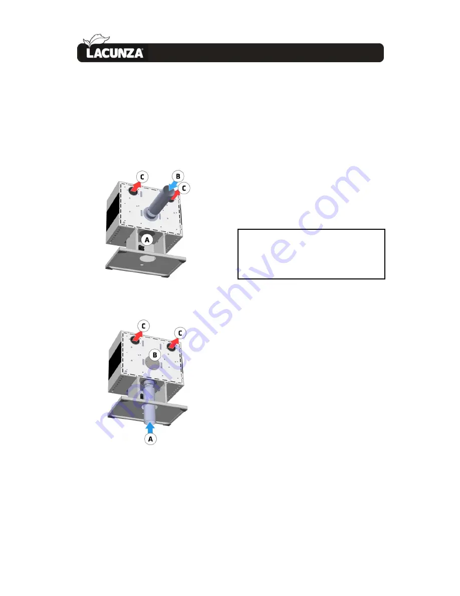
Figure No.8 -
Combustion air intake ducted
from the rear part (B). Lower intake (A) closed.
Figure No.9 -
Combustion air intake ducted
from the lower part (A). Rear intake (B) closed.
If we want to duct the combustion air
intake from the lower part, we need to
unscrew the circular cover from the lower
part (A) and screw it in the rear part (B).
2.3.7.1.
Combustion-air intake and hot-air
output installation options
Different installation systems need to
be borne in mind depending on the source
of combustion air (air from outdoors or
from inside the room in which the
appliance is fitted) and the hot-air output
system (air output by natural convection or
by forced convection involving a fan) to
ensure that the appliance works properly.
There now follows a description and image
of each of these options:
A:
Lower ductable combustion air intake
(Ø120mm)
B:
Rear ductable combustion air intake
(Ø120mm)
C:
Rear ductable hot air outlets (Ø120mm)
Summary of Contents for Titanium Plus
Page 1: ...Titanium Plus Instruction Book...
Page 26: ...BASIC BREAKDOWNS 25 6 BASIC BREAKDOWNS...
Page 27: ...BASIC BREAKDOWNS 26 6...
Page 28: ...BASIC BREAKDOWNS 27 6...
Page 29: ...DECLARATION OF PERFORMANCE 28 7 DECLARATION OF PERFORMANCE...
Page 30: ...DECLARATION OF PERFORMANCE 29 7...
Page 31: ...CE MARK 30 8 CE MARK...


