48
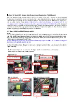
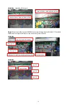
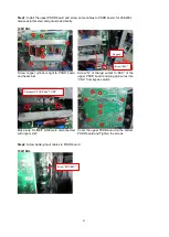
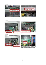
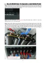
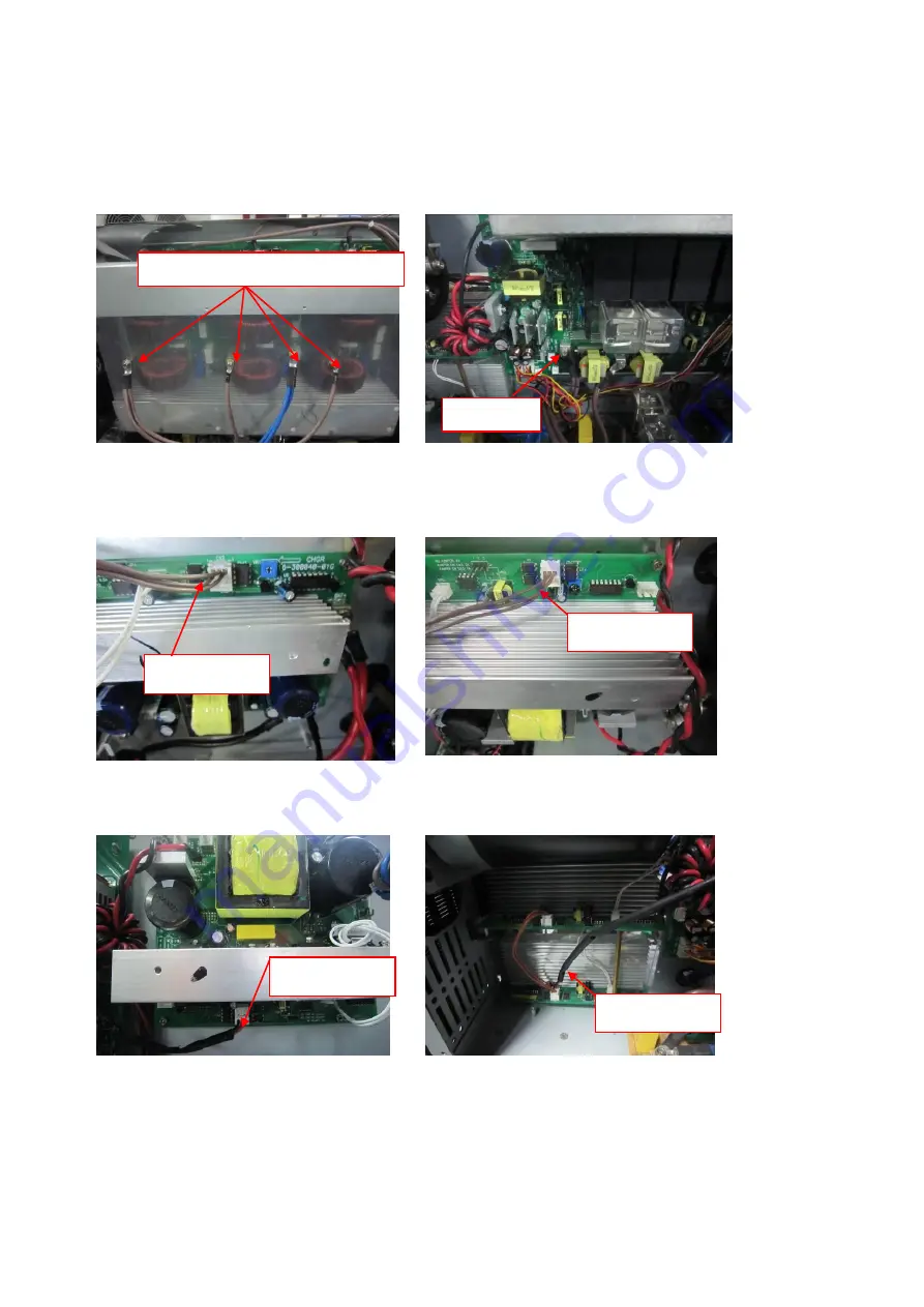
“I/N” of the bottom PSDR board and screw “S
LINE” and “T LINE” of the upper PSDR board.
Then, re-assemble the upper PSDR board
and the control board and the communication
board, and connecting related cables finally.
20K/20KL
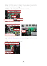
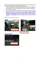
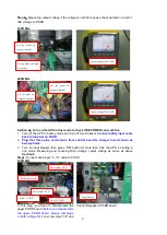
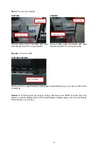
Step 2:
Plug this 3 pins control wire to charger board
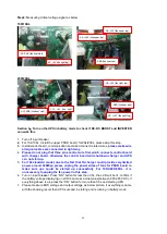
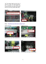
10K
:
1A Charger
10KL
:
4A Charger
This 3 pin wire is from “CN7” of contrl board
This 3 pin wire is from “CN7” of contrl board
20K
20KL
This 3 pin wire is from “CN7” of contrl board
This 3 pin wire is from “CN7” of contrl board
Plug this 3 pin wire
Screw Input “R I/P”&“S I/P”&“T I/P”&“N”
Plug this 3 pin wire
Screw Bypass
Plug this 3 pin wire
Plug this 3 pin wire
Summary of Contents for G31 10K
Page 37: ...37 ...

