53
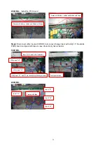
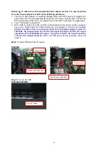
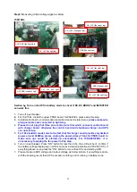
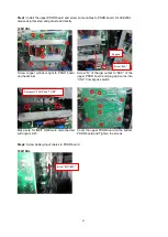
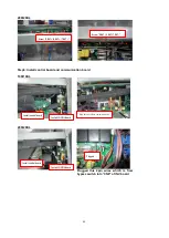
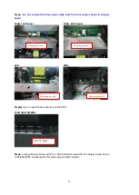
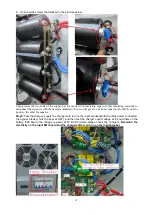
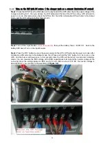
b. Unscrew the screws that marked in the pincture below:
Then protect the two ends of the copper bar for neutral with insulating tape (or other insulating material) to
disconnect the capacitor with the neutral completely, then we will get two electronic capacitors for BUS, one for
positive, the other for negative.
Step5:
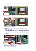
Test the charger: supply the charger with turn on the input breaker(With the utility power connected,
the bypass breaker must be kept at OFF), and then test the charger ouput voltage at the terminals on the
battery EMI board, the voltage is about 245V DC,Otherwise,please check the chargers.
Becareful the
electricity on the Input EMI board and the chargers after you turn on the input breaker.
Summary of Contents for G31 10K
Page 37: ...37 ...

