43
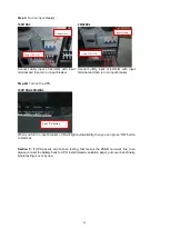
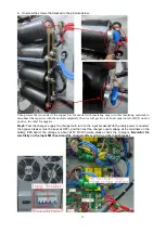
Step1:
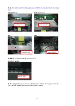
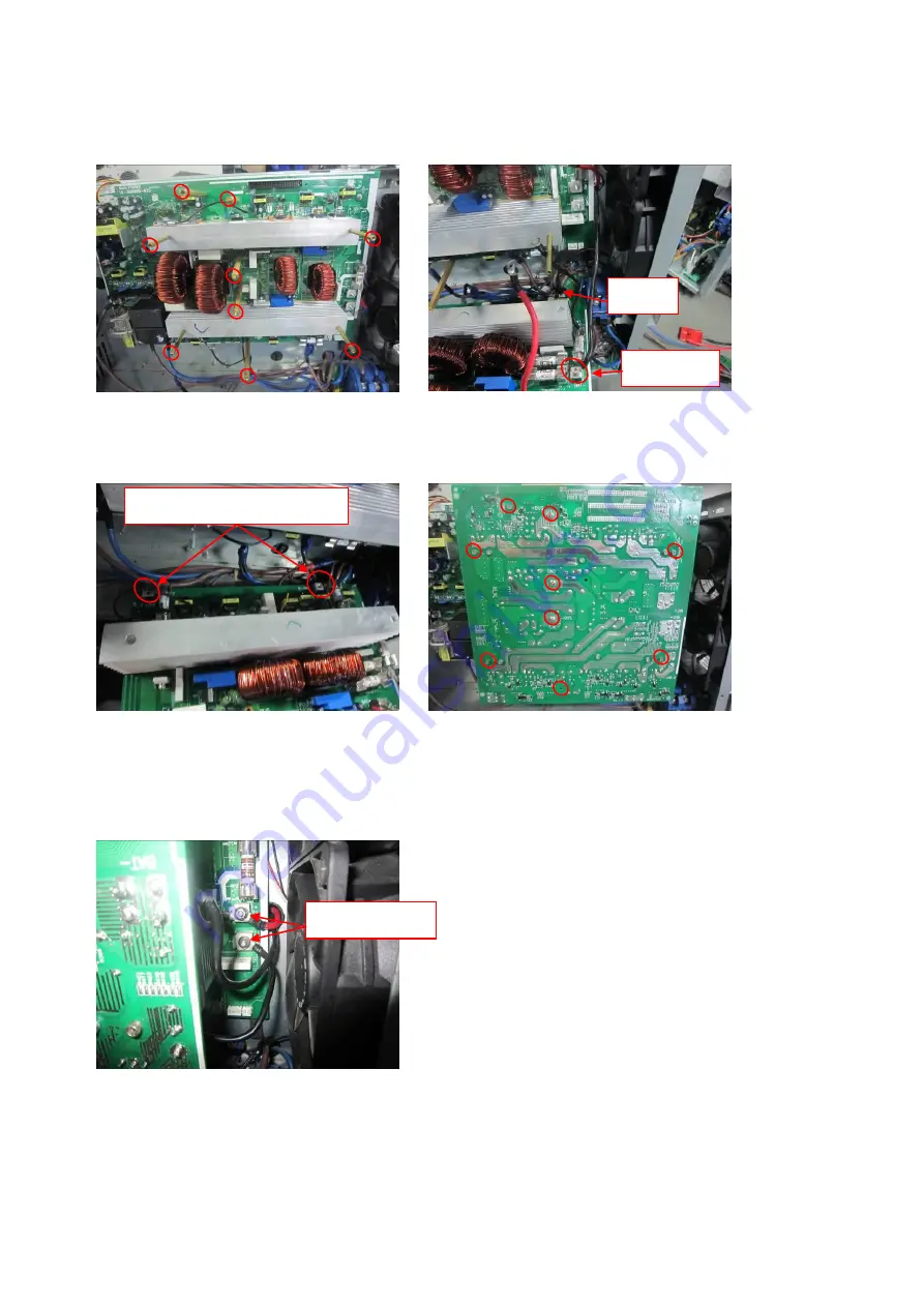
Install the upper PSDR board and screw some cables to PSDR board, for 20k/20KL,
please skip this step and goto step2 directly.
10K/10KL
Screw copper cylinders tight to PSDR board
and heat sinks
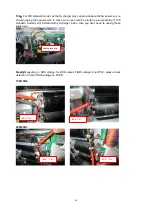
Screw “N” of charger output to “BAT-“ of the
upper PSDR board and plug 2pin wires into
“CN2” from bypass switch
Make sure S LINE/T LINE were disconnected
with input L2/L3
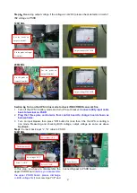
Cover the upper PSDR board on the bottom
PSDR board and Tighten the screws
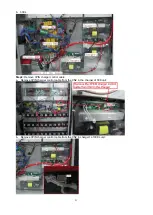
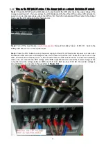
Step2
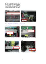
: Screw battery input cables to PSDR board
10K/10KL
Disconnect “S LINE” and “T LINE”
Screw “BAT-“
Plugged
Screw “BAT+/BAT-“
Summary of Contents for G31 Series
Page 37: ...37 ...


