20/54
Mounting and operating instructions Electric transporter BLACK LINE
Assembly
5.2
Preparation for mounting
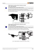
Countersink of the mounting holes in the trough
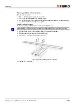
For standing or hanging mounting with clamping of a trough to a profile rail, drilling and counter-
sinking mounting holes is not required.
Required tool:
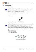
Mounting tool 2299.10.00.01.05 or 2299.10.00.01.06 (see chapter 5.3 "Mounting material"
on page 22).
Ring wrench 10 mm for countersunk screw M5
Allen wrench 4 mm for countersunk screw M5
Ring wrench 13 mm for countersunk screw M6
Allen wrench 5 mm for countersunk screw M6
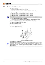
Eight threaded holes are located on the carriage of the electric transporter. The four outer
threaded holes must be used for mounting a single trough.
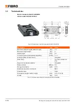
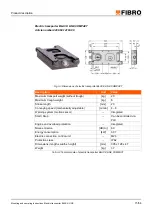
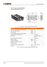
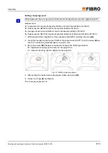
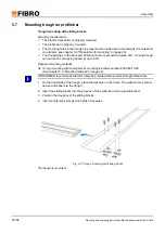
1. Mark the position of the holes on the trough (for hole pattern of the relevant electric trans-
porter, see chapter 3.3 "Technical data" on page 14).
2. Drill holes.
a) Hole diameter 6 mm for countersunk screw M5.
b) Hole diameter 8 mm for countersunk screw M6.
3. Insert countersunk screw into the hole from above.
4. Screw the counterpart onto the countersunk screw from below.
5. Hold the counterpart with the ring wrench.
6. Screw the countersunk screw into the counterpart using the Allen wrench and tighten.
7. Unscrew the countersunk screw and the counterpart.
8. Perform steps 3 to 7 in each hole.
The countersinks are complete.
1.
2.
3.
4.
5.
6.

