30/54
Mounting and operating instructions Electric transporter BLACK LINE
Assembly
5.4
Mounting electric transporter
Mounting requirements:
The mounting surface must be horizontal and flat.
The electric transporter must not be mounted in a tilted or inclined position.
Required mounting material:
4 fixing screws M6x40 for electric transporter 2299.6x.18100.00
4 fixing screws M8x50 for electric transporter 2299.6x.14100.00
4 fixing screws M8x70 for electric transporter 2299.6x.12100.00
FIBRO GMBH recommends that all screws be provided with medium-strength thread lock.
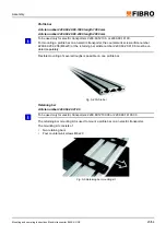
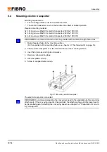
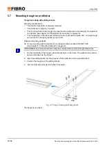
1. Make threaded holes in the mounting surface.
(For hole pattern of the mounting holes, see chapter 3.3 "Technical data" on page 14).
2. Place electric transporter over the threaded holes in the mounting surface.
3. Insert fixing screws and tighten crosswise.
4. Remove yellow warning tape.
5. Unscrew plastic oil cap.
6. Screw in supplied metal oil cap.
Fig. 5-13 Mounting electric transporter
The electric transporter is mounted.
FIBRO GMBH recommends adjusting the conveying speed to the application before mounting
attachments. If the conveying speed is changed later, the attachments would otherwise have to
be dismantled again (for setting the conveying speed, see chapter 5.2 "Preparation for mount-
ing" on page 20).

