Mounting and operating instructions Electric transporter BLACK LINE
31/54
Assembly
5.5
Mounting single trough
Mounting requirements:
The electric transporter is properly mounted.
The mounting holes in the trough are present and provided with a countersink (for holes and
countersink, see chapter 5.2 "Preparation for mounting" on page 20).
The trough slope in the transport direction must not exceed the value of 8°. A rising trough
can reduce the conveying speed by up to 50%.
Required mounting material:
Standard trough mounting
kit (see chapter 5.3 "Mounting material" on page 22).
4 countersunk screws M5x8 and 4 washers for electric transporter 2299.6x.18100.00
4 countersunk screws M6x10 and 4 washers for electric transporter 2299.6x.14100.00
4 countersunk screws M6x10 and 4 washers for electric transporter 2299.6x.12100.00
FIBRO GMBH recommends that all screws be provided with medium-strength thread lock .
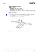
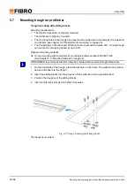
1. Remove plastic film from the washers.
2. On the underside of the trough, place the washers on the holes. The washers are self-ad-
hesive and adhere to the trough.
3. Position trough over the threaded holes of the electric transporter, insert countersunk
screws and tighten crosswise.
Fig. 5-14 Mounting single trough
The trough is mounted.
If troughs are long, FIBRO GMBH recommends installing suitable trough support (see chapter
5.8 "Trough support" on page 37).
1.
2.
3.


