background image

Mounting and operating instructions Electric transporter BLACK LINE

37/54

Assembly

5.8

Trough support

Depending on the length of a trough and the weight of the conveyed material, suitable trough 
support must be installed.
Installing trough support is at the discretion of the operator.
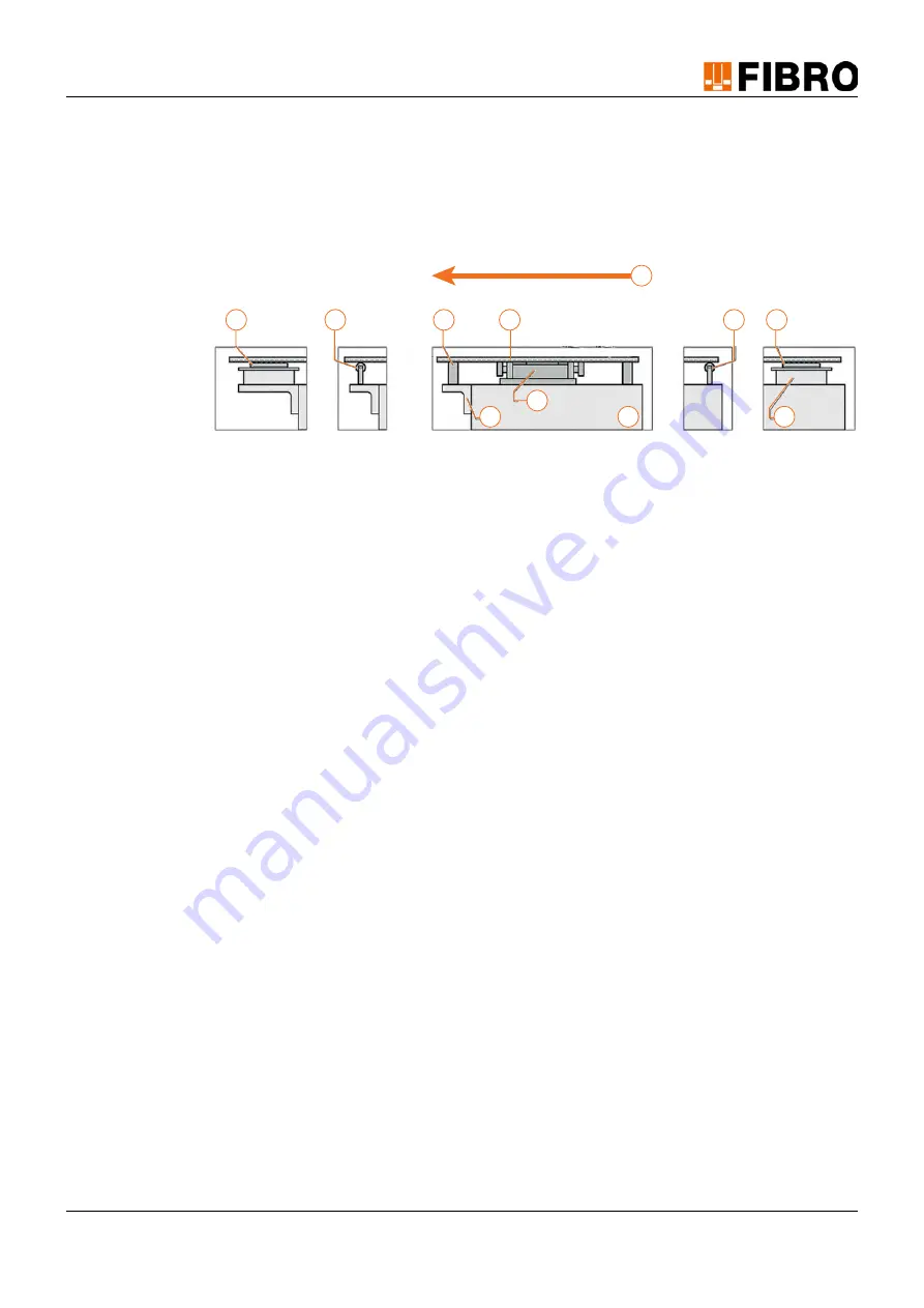
Example of trough supports:

Fig. 5-20 Trough supports

1

Electric transporter

2

Mounting surface

3

Support bracket

4

Spacer

5

Ball  guide

6

Support roller

7

Sliding guide

8

Trough

9

Transport device

5

6

7

3

1

4

8

6

5

2

9

Summary of Contents for Fibro BLACK LINE Series

Page 1: ...Y MEMBER OF THE LAEPPLE GROUP MOUNTING AND OPERATING INSTRUCTIONS ELECTRIC TRANSPORTER BLACK LINE 2299 60 12100 00 2299 60 14100 00 2299 60 18100 00 Mounting and operating instructions Electric transp...

Page 2: ...his manual including the title page 54 These instructions are valid for the product 2299 60 12100 00 2299 60 14100 00 2299 60 18100 00 Electric transporter BLACK LINE This document was created by FIBR...

Page 3: ...rsonnel 9 2 1 3 Personnel requirements 10 2 2 Residual risks 11 3 Product description 12 3 1 System structure and equipment 12 3 2 Function 13 3 3 Technical data 14 3 3 1 Type plate 17 3 3 2 Tightenin...

Page 4: ...ance work 41 9 3 Inspection 42 9 4 Cleaning 42 9 5 Maintenance 43 9 6 Repairs 43 10 Disassembly and disposal 44 11 Service and spare parts 45 11 1 Service 45 11 2 Spare parts ordering 45 11 3 Spare pa...

Page 5: ...ny operating the product is responsible for protective systems or safety devices cov ering the operation of the whole system Proper use also includes Reading these instructions Complying with the safe...

Page 6: ...are not updated automatically We reserve the right to make changes to the data and images in these instructions in the course of further technical development FIBRO GMBH can supply the current issue T...

Page 7: ...lled before executing handling instructions Contains information on tools operating materials or tools required for the execution of re pair work 1 6 3 Figures The figures in these instructions are ex...

Page 8: ...ange signal bar with the signal word WARNING designates a haz ard with a medium risk level which if not avoided might result in death or severe injury CAUTION A safety notice on a yellow signal bar wi...

Page 9: ...ified personnel are persons who due to their education experience training and knowl edge of relevant standards provision accident prevention regulations and operating condi tions are authorised to pe...

Page 10: ...tool activity working method or practice is not expressly suggested by FIBRO GMBH users must ensure it is safe both for themselves and others It must also be ensured that the product is not damaged or...

Page 11: ...nd cause an ex plosion The product is not suitable for use in explosion hazard areas Use in explosion hazard areas is prohibited Serious through to fatal injuries due to the consequences of an explosi...

Page 12: ...transporter BLACK LINE MAX 2299 60 12100 00 System The product consists of Electric transporter Mounting elements for electric transporter mounting material optional Mounting elements for trough moun...

Page 13: ...sporter With FIBRO GMBH this control unit including the connection cable for the connection socket and the signal cable for data exchange with external devices is available 3 2 Function A trough or co...

Page 14: ...ter BLACK LINE MINI Description Unit Value Maximum transport weight without trough kg 10 Maximum trough weight kg 4 Stroke length mm 20 Conveying speed mechanically adjustable m min 4 8 Warning system...

Page 15: ...ACK LINE COMPACT Description Unit Value Maximum transport weight without trough kg 20 Maximum trough weight kg 8 Stroke length mm 20 Conveying speed mechanically adjustable m min 4 8 Warning system mo...

Page 16: ...LINE MAX Description Unit Value Maximum transport weight without trough kg 40 Maximum trough weight kg 16 Stroke length mm 20 Conveying speed mechanically adjustable m min 4 8 Warning system motion s...

Page 17: ...ate is attached to the BLACK LINE electric transporter The information on the name plate must be given for all questions and orders Fig 3 5 Type plate 3 3 2 Tightening torques If not otherwise specifi...

Page 18: ...any must be informed immediately and the transport company must verify the damage 4 2 Interim storage Only store when dry in its original packaging and in enclosed rooms Storage temperature 20 C 60 C...

Page 19: ...tallation can lead to damage to the product and consequently to hazards for per sons Assembly work is only permitted to be carried out by qualified personnel Work to connect the electrical energy is o...

Page 20: ...M6 Eight threaded holes are located on the carriage of the electric transporter The four outer threaded holes must be used for mounting a single trough 1 Mark the position of the holes on the trough f...

Page 21: ...nch SW13 for electric transporter 2299 6x 14100 00 and 2299 6x 18100 00 1 With the aid of the screwdriver or the socket wrench SW36 unscrew the oil cap A 2 Using the hexagon socket wrench SW6 or the s...

Page 22: ...the trough The mounting tool consists of Countersunk screw Counterpart Fig 5 2 Mounting tool Standard trough mounting Article number 2299 69 10 1x For electric transporter 2299 60 18100 00 or 2299 61...

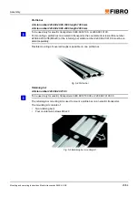
Page 23: ...rew article number 2299 69 20 02 06 M6x20 or the retaining bar article number 2299 69 20 01 06 must be or dered separately Flexible mounting of several troughs is possible on one profile bar Fig 5 4 P...

Page 24: ...e used only for electric transporter 2299 60 14100 00 or electric transporter 2299 60 12100 00 The trough mounting with sliding blocks mounting kit is used for mounting a trough on a profile bar The m...

Page 25: ...12100 00 or 2299 60 14100 00 Due to its simple clamping principle the standing trough mounting kit enables flexible mounting of a trough on the top of a profile bar without additional machining The m...

Page 26: ...60 14100 00 Due to its simple clamping principle the hanging trough mounting kit enables flexible mounting of the trough on the bottom of a profile bar as well as mounting of the electric transporter...

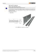
Page 27: ...sed only for electric transporter 2299 60 12100 00 The angle profile for clamping rail mounting kit is welded onto the bottom of a trough and due to its simple clamping principle enables flexible moun...

Page 28: ...0 1500 22299 69 30 2000 To be used only for electric transporter 2299 60 12100 00 A clamping rail is used to quickly switch between several troughs The mechanical clamping lever clamps the troughs on...

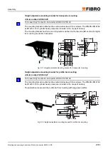
Page 29: ...ounting options defined on the top side left centre and right for mounting an electric transporter Fig 5 11 Height adjustable mounting bracket for transporter mounting Height adjustable mounting brack...

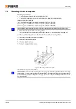
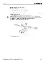
Page 30: ...ed with medium strength thread lock 1 Make threaded holes in the mounting surface For hole pattern of the mounting holes see chapter 3 3 Technical data on page 14 2 Place electric transporter over the...

Page 31: ...unk screws M5x8 and 4 washers for electric transporter 2299 6x 18100 00 4 countersunk screws M6x10 and 4 washers for electric transporter 2299 6x 14100 00 4 countersunk screws M6x10 and 4 washers for...

Page 32: ...s must be on the groove side Mounting requirements The electric transporter is properly mounted The profile bar is available in the required length The mounting holes in the profile bar with countersi...

Page 33: ...ole pattern of the fastening holes see chapter 3 3 Technical data on page 14 Required mounting material Retaining bar mounting kit article number 2299 69 20 01 06 FIBRO GMBH recommends that all screws...

Page 34: ...e value of 8 A rising trough can reduce the conveying speed by up to 50 Required mounting material Trough mounting with sliding blocks mounting kit article number 2299 69 10 20 See chapter 5 3 Mountin...

Page 35: ...BH recommends that all screws be provided with medium strength thread lock 1 Insert the sliding blocks into the grooves of the profile bar and pre position them 2 Mount the mounting bracket on the tro...

Page 36: ...H recommends that all screws be provided with medium strength thread lock 1 Insert the sliding blocks into the grooves of the profile bar and pre position them 2 Mount the mounting bracket on the trou...

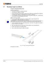
Page 37: ...ht of the conveyed material suitable trough support must be installed Installing trough support is at the discretion of the operator Example of trough supports Fig 5 20 Trough supports 1 Electric tran...

Page 38: ...sioning 6 COMMISSIONING The product is designed for installation in a machine or system in accordance with its intended use The product is commissioned together with the machine or system in which it...

Page 39: ...orter BLACK LINE 39 54 Operation 7 OPERATION 7 1 Operation The product is designed for installation in a machine or system in accordance with its intended use Operation is the responsibility of the di...

Page 40: ...ld require the assistance of our costumer service we would ask you to provide the following information Serial number from type plate FIBRO GMBH see chapter 3 3 1 Type plate on page 17 Description of...

Page 41: ...structions with regards to the maintenance may be carried out by the staff of the operator This staff has to be trained and authorised for the intended tasks All further work and repairs may as a rule...

Page 42: ...pecified cleaning interval The time of a cleaning operation is dependent on Daily operating time Production conditions Operational environment 1 Inspect product for contamination 2 Clean product if ne...

Page 43: ...fully 4 Unscrew oil cap 5 Turn over electric transporter and let the oil run into a suitable container for at least 30 min utes 6 Attach electric transporter 7 Fill with new oil 8 Screw on oil cap 9 P...

Page 44: ...disposal of assemblies can cause environmental damage and lead to prosecution In any case the assemblies must be disposed of in accordance with the relevant national and regional laws and guidelines C...

Page 45: ...pare parts ordering Bei der Bestellung von Ersatzteilen bitten wir um folgende Angaben Name address mailing address Exact name of the machine Serial number from type plate see chapter 3 3 1 Type plate...

Page 46: ...299 60 14100 00 02 Engine cover Black Line 2299 60 14100 00 2299 60 18100 00 02 Engine cover Black Line 2299 60 18100 00 2299 60 12100 00 03 Carriage Black Line 2299 60 12100 00 2299 60 14100 00 03 Ca...

Page 47: ...ig 5 7 Standing trough mounting kit 25 Fig 5 8 Hanging trough mounting kit 26 Fig 5 9 Angle profile for clamping rail mounting kit 27 Fig 5 10 Clamping rails 28 Fig 5 11 Height adjustable mounting bra...

Page 48: ...tallation in the context of this Directive FIBRO GMBH states in the declaration of installation which essential requirements of this direc tive were applied and complied with In addition the declarati...

Page 49: ...e the special documents to national authorities in electronic form upon justified request Person resident in the Community authorised to compile the relevant technical documents FIBRO GMBH Wendelin Le...

Page 50: ...50 54 Mounting and operating instructions Electric transporter BLACK LINE Appendix 13 2 Personal notes...

Page 51: ...porter BLACK LINE 51 54 Appendix 13 3 Maintenance plan Interval Years or h Qualification Task 3 15 000 Trained personnel Oil change daily weekly monthly quarterly half yearly yearly if required Task x...

Page 52: ...ts technical 49 E electric transporter components 12 Energy consumption 14 15 16 Engine protection 14 15 16 H Humidity maximum 18 I Injuries preventing 8 L Lubricant 43 Lubricant quantity 43 M misuse...

Page 53: ...nts special 49 Temperature range Operation 5 thread lock 31 tightening torque screws 17 tools 10 Transport damage 18 transport weight maximum 14 15 16 Trough mounting with sliding blocks 24 34 trough...

Page 54: ...a com FIBRO ASIA PTE LTD Business Area Standard Parts 9 Changi South Street 3 07 04 Singapore 486361 Singapore T 65 65 43 99 63 info fibro asia com 09 2019 Order No 2 7826 00 0919 0100000 FIBRO INC Bu...

Reviews: