© copyright 2005
(P/N)12-249 v2 • 9/08
Kaba Mas LLC
page 2 of 8
Opening SMARTLINC Set-up Software
Once all of the software has been installed on the computer, it is time to begin setting up the Logic Module and lock(s). Open the set-
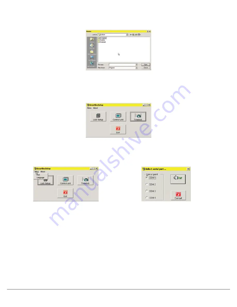
up software. Using either Windows Explorer or the START button, find the LA GARD folder on the hard drive. Within the LA GARD folder
there are 3 folders labeled DSTUpdate, SMARTLINC and Total Audit. Open the SMARTLINC folder and double click on the file named
SMARTLINCSETUP (see Screen 1).
SMARTLINC Set-up Software
The opening window of the set-up software allows the choice of Lock Set-up, Control Unit (Logic Module) Set-up, Time Lock Set-up and
Exiting the Set-up software (see Screen 2).
COM Port Set-up
The COM port must be selected before beginning set-up. Select the appropriate COM port from the Port Menu. The default is COM 1 (see
Screens 3 & 4).
LOCK SET-UP
To set up the locks, click on the Lock Set-up button on the opening screen (see Screen 2). A window with the default configuration will
appear (see Screen 5). In this window, select the features to be enabled on the locks.
• Select the lock ID for the lock to be programmed. Marking the lock itself with its ID number is recommended.
• Each lock can be assigned a serial number in this window. Checking this box allows the option of entering a Fixed Field, which is
alphabetical, and a Variable Field, which is alphanumeric. If entered, this information will be shown on the audit.
• If Dual Code is installed, User #2 is automatically installed (see screen 6). If installed, two codes will be required not only to open the
lock, but to access the Manager Menu options as well.
• Users can only be configured on the Logic Module if they have been set up as Deleted in this window. A Deleted User is a user number
ready for installation; a Blocked User is a user number that will be unavailable for installation. Installed is an automatic feature available
only for User #2 when setting the unit up in Dual Code.
• Time Delay open window and delay times may be set up in this window or from the Logic Module.
• If, when installed, there is a lock that will take longer than 4 seconds to reach and open, the use of the Open Device is recommended.
The Open Device will hold the signal going to the lock for one (1) minute or until the outer door has been opened and the Open
Device depressed.
NOTE: Open Device and Duress Alarm cannot work at the same time.
• Once all of the features for this lock have been selected, save the set-up to a file for later use. If a file has already been saved, it may be
opened from this window as well.
Screen 1
Screen 2
Screen 3
Screen 4


