background image

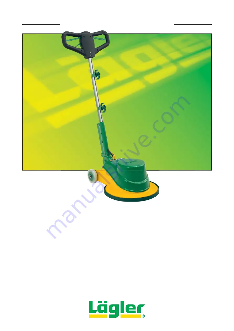
SINGLE - THE SINGLE-DISC SANDING MACHINE

SINGLE

English / Englisch

Operation, 

Maintenance, Safety

Translation of the original operating instructions 

for the single-disc sanding machine

00.850.20.002     01.02.2013

*00.850.20.002*

Summary of Contents for SINGLE

Page 1: ...E SINGLE DISC SANDING MACHINE SINGLE English Englisch Operation Maintenance Safety Translation of the original operating instructions for the single disc sanding machine 00 850 20 002 01 02 2013 00 85...

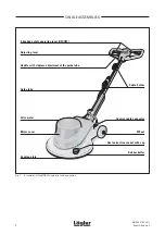
Page 2: ...INGLE single disc sanding machine Cable holder 2 handed safety operating lever ON OFF Adjusting lever Handle with stepless adjustment of the guide tube Drive motor Sanding plate Motor cover Guide tube...

Page 3: ...replacing the cable holder 14 4 5 Attaching an external vacuum cleaner 14 4 6 Attaching the fluffy sealing strip as protection against dust 15 5 Transport and storage 16 5 1 Dismantling and assemblin...

Page 4: ...idents 1 3 INTENDED USE OF THE MACHINE The SINGLE single disc sanding machine is suitable for sanding wooden and cork floors and for work on floor underlays in the pro fessional and DIY rental sectors...

Page 5: ...atmosphere e g while working with the machine or emptying out the dust This could cause a dust explosion The mains connection cable must be kept out of the work area in order to prevent mechanical or...

Page 6: ...uide tube 265 mm 10 Total length without guide tube 615 mm 24 Height above sanding plate 46 mm 1 Total width 435 mm 17 1 8 Weight of the machine with sanding plate 45 kg 99 lbs Workplace related noise...

Page 7: ...effect please check the condition of the wearing parts listed below at regular intervals Replace Velcro attachment disc on the sanding plate if worn or damaged Replace paper retaining disc if worn or...

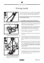
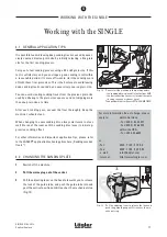
Page 8: ...r on the handle towards you to release the lock of the guide tube and push the guide tube into and past the vertical position until it reaches the mechanical stop Fig 3 5 Release the adjusting lever s...

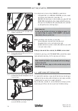
Page 9: ...t of a sepa rate vacuum cleaner please see also Section 4 5 Attaching an external vacuum cleaner 3 3 STARTING THE MACHINE NOTE Please read this section very carefully It contains important safety inst...

Page 10: ...n you have made these checks the SINGLE can be started Pull both the start levers AT THE SAME TIME and hold the handle tight with both hands Fig 12 The machine will start up Never allow the machine to...

Page 11: ...ze used by adhering to the grain size sequence and not skipping more than one grain size at a time After each sanding pass vacuum the floor thoroughly Keep the machine s wheels clean When changing to...

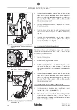
Page 12: ...ug out of the socket 3 Pull the adjusting lever on the handle towards you to release the lock of the guide tube and push the guide tube into and past the vertical position until it reaches the mechani...

Page 13: ...orn sanding disc from the sanding plate and lay them to one side 7 Place a new sanding disc on the sanding plate and push the fastening screw with paper retaining disc into the sanding plate Fig 19 8...

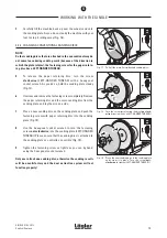
Page 14: ...sliding block loosely onto the screw 3 Push the sliding block into the groove on the guide tube and tighten the screw As you do so the sliding block turns so that the cable holder is clamped in place...

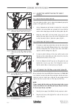
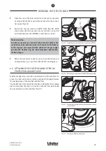
Page 15: ...able cable binders for this purpose 5 When the machine is ready for use as described in the pre ceding sections you can start with the first sanding pass 4 6 ATTACHING THE FLUFFY SEALING STRIP AS PROT...

Page 16: ...de tube back into a horizontal position 6 Use a hexagonal socket wrench to release the four fastening screws at the base of the guide tube Steady the guide tube with one hand as you do so Fig 30 To re...

Page 17: ...e pro cedure in order to ensure that the machine is in full working order and produces the customary high quality sanding finish Clean the machine s wheels Clean all dust or other residues off the mov...

Page 18: ...k absorber Fig 33 7 Replace the parts that are damaged or worn 8 The gear of the SINGLE is maintenance free and contains a special oil The incorrect volume of oil can cause severe damage to the gear F...

Page 19: ...l follow the instructions above in reverse order 6 4 REPLACING THE CENTERING DOME ON THE SANDING PLATE 1 Remove the sanding plate from the SINGLE and lay it on the floor with the flat side down 2 Turn...

Page 20: ...being in good working order Ensure that only original L GLER spare parts are used for main tenance work After sales servicing should only be performed by L GLER or by a L GLER approved workshop The s...

Page 21: ...2 5 sq mm and excessively long supply lines should be avoided if necessary use a transformer Part no 708 00 00 100 for 230 Volts MACHINE RUNS BADLY The machine runs but with no or insufficient sanding...

Page 22: ...a potential safety hazard Be aware of environmental influences Never leave the machine out in the rain Do not use the machine in humid or wet atmospheres Ensure that good lighting is provided Never u...

Page 23: ...ent Use safety gear Use respiratory masks with filter class P3 when working in dust laden atmospheres Only use the cable for its intended purpose Never use the cable to carry or pull the machine or to...

Page 24: ...r they are jamming whether any parts are broken whether all other parts are correctly mounted and all other condi tions which could influence operation of the machine are correct Unless otherwise spec...

Page 25: ...SINGLE 01 02 2013 English Englisch NOTES 25...

Page 26: ...ww laegler com 1 2 kW 230 V 50 CPS 1 2 kW 230 V 60 CPS Phone 0049 7135 98 90 0 Fax 0049 7135 98 90 98 C S A C Ha Hi A B tarting capacitor Running capacitor Main winding uxiliary winding K1 Contactor K...

Page 27: ...ase AC motor Correct rotating direction of the motor Look to the gear unit Look to the fan wheel F1 Fuse S1 Switch H1 Lamp K1 Contactor K2 Relay Phone 0049 7135 98 90 0 Fax 0049 7135 98 90 98 6 5 4 K1...

Page 28: ...SINGLE 01 02 2013 English Englisch SPARE PARTS 28 11...

Page 29: ...80 200 Dust extraction socket 2 000 65 43 252 Motor cable 3 x 2 5 mm 3 000 65 71 040 Integrated socket 4 7500 1003 010 Screw 5 850 05 09 105 Wheel 6 0125 1012 000 Washer 7 0471 0012 000 Circlip 8 850...

Page 30: ...SINGLE 01 02 2013 English Englisch SPARE PARTS 30 11...

Page 31: ...English Englisch SPARE PARTS Item Part number Description 1 0912 1006 016 Screw 2 0125 1006 000 Washer 3 850 20 28 105 Cable holder 4 850 20 29 100 Sliding block 5 7984 1008 030 Screw 6 900 70 25 105...

Page 32: ...SINGLE 01 02 2013 English Englisch SPARE PARTS 32 11...

Page 33: ...00 65 80 061 Fuse 6 3 A 5 000 65 82 010 Fuse holder 6 000 65 20 012 Contactor 7 000 65 20 230 Relay 8 850 64 06 100 Adapter mounting 9 850 64 07 205 Shock absorber 10 850 64 08 100 Plate mounting 11 1...

Page 34: ...SINGLE 01 02 2013 English Englisch SPARE PARTS 34 11...

Page 35: ...0 02 10 100 Sanding plate SINGLE complete 1 850 02 06 200 Centering dome 2 850 02 11 100 Velcro coating for pad and Velcro sanding disc two parts necessary 3 850 02 13 105 Velcro ring flexible 6 850 0...

Page 36: ...SINGLE 01 02 2013 English Englisch SPARE PARTS 36 11...

Page 37: ...screw wrench 6 mm 4 000 93 12 052 Hexagonal socket screw wrench 5 x 150 mm 5 000 65 53 251 Extension cable 3 x 2 5 mm 10 m long 6 000 01 20 010 Respiratory protection mask P3 7 701 10 00 100 Impact t...

Page 38: ...SINGLE 01 02 2013 English Englisch NOTES 38...

Page 39: ...Signature and company stamp Date of test and maintenance work Signature and company stamp Date of test and maintenance work Signature and company stamp Date of test and maintenance work Signature and...

Page 40: ...EG The following harmonized standards have been applied DIN EN ISO 12100 Safety of machinery General principles for design Risk assessment and risk reduction DIN EN 60204 1 Safety of machinery Electr...

Reviews: