SINGLE 01.06.2019
English / Englisch
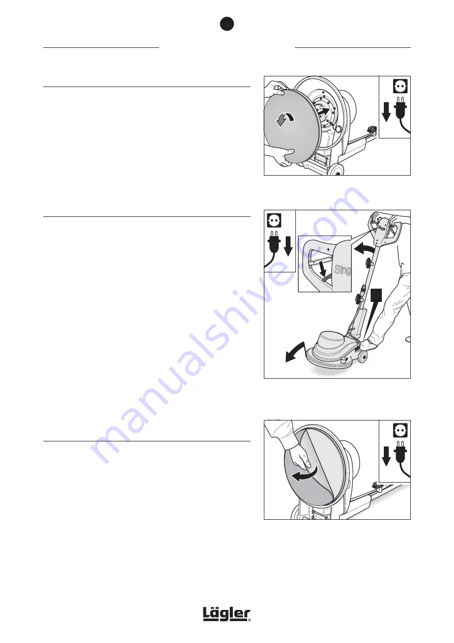
Fig. 21
Push on the sanding plate (1) and turn it
coun-
terclockwise
until it reaches the mechanical
stop (2).
22
11
WORKING WITH THE SINGLE
5.2.2 INSERTING THE SANDING PLATE
1
In order to insert the sanding plate push it centrally onto the
gear mount (fig. 21, 1) and turn it
counterclockwise
until it
reaches the mechanical stop (fig. 21, 2).
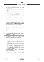
2
Make sure that the adjusting lever is in the
lower position
(fig. 22, 1). Carefully tilt the machine forwards over the wheels
and onto the sanding plate. As you do so, steady the machine
with your foot to stop it rolling away (fig. 22, 2).
5.3 CHANGING THE SANDING DISC
Depending on the type of sanding process you wish to perform,
different grits can be selected. In order to change the abrasive,
proceed as follows:
1
Switch off the machine and pull the power plug out of the
socket!
2
Pull the adjusting lever on the handle towards you to release
the lock of the guide tube (fig. 18, 1), and push the guide
tube into and past the vertical position until it reaches the
mechanical stop (fig. 18, 1).
3
Release the adjusting lever so that the guide tube can engage
again (fig. 19, 1). Carefully tilt the machine backwards on the
wheels. As you do so, steady the machine with your foot to
stop it rolling away (fig. 19, 2).
Please ensure that the machine is stable before commencing
work!
5.3.1 CHANGING VELCRO-BACKED SANDING DISCS
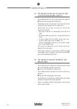
4
Pull the worn Velcro-backed sanding disc off the Velcro
attachment ring of the sanding plate (fig. 23).
5
Press the new Velcro-backed sanding disc with the Velcro
side against the Velcro attachment ring of the sanding plate.
As you do so, please ensure that the Velcro-backed sanding
disc is attached to the sanding plate as centrally as possible.
6
Make sure that the adjusting lever on the handle is in the
lower position
(fig. 22, 1). Carefully tilt the machine forwards
over the wheels and onto the sanding plate. As you do so,
steady the machine with your foot to stop it rolling away
(fig. 22, 2).
Fig. 23
Pull off the worn Velcro-backed sanding disc.
5
Fig. 22
Make sure
that the adjusting lever is in the
lower
position (1). Carefully tilt the machine forwards
and secure it against rolling away at the same
time (2).
!
22
11
27


