Dake Corporation
1809 Industrial Park Dr
Grand Haven, MI 49417
976200-2, 976202-2
13
REV112019
SETTING HEAD PARAMETERS
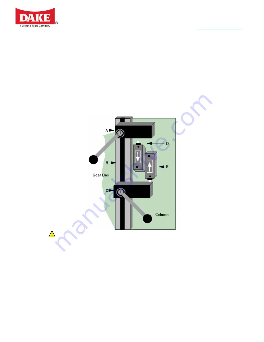
This is a dependable method of reducing “dead air” cutting. The picture above illustrated the
four basic parts of the head positioning system.
A:
Lower limit adjustable cam block.
B:
Machined T-slot way that the cam moves vertically in.
C:
Upper head limit adjustable cam block.
D:
Limit switch that controls the lower setting. When the switch is activated the blade stops
and the head returned to the upper setting.
E:
Upper limit switch, this controls the head
NEVER MAKE THESE ADJUSTMENTS WITH THE BLADE ROTATING.
NEVER DEPRESS THE LIMIT SWITCHES WITH YOUR FINGER, YOUR FINGER COULD BE
CRUSHED OR AMPUTATED BETWEEN THE LIMIT SWITCH AND CAM BLOCK.
1. To set the parameters move the cams to the extreme positions and tightened down. (The
top cam to the highest position and lower cam to the lowest position.)
2. Turn the speed selector to “0”, or “OFF”.
3. Place material in the main vise and up to the blade path, move the head feed control
valve to "0”.
Do not place material under the blade path.
a. Make sure the emergency button is not engaged.
4. Press the yellow button and slowly open the feed valve. As the head descended
downward toward the material, close the head feed flow control valve to stop the head
just above the material.
Never have the blade adjusted closer than 1/2" to the
material to allow proper clearance.


