Dake Corporation
1809 Industrial Park Dr
Grand Haven, MI 49417
976200-2, 976202-2
14
REV112019
5. After stopping the head, loosen the upper head setting cam (the cam block on bottom),
and raise the cam up to where it touches the limit switch without depressing the limit
switch button. Securely tighten this cam down. (The power of the head feed cylinder will
move this limit if the cam is not securely tightened.)
Note: Never lock the cam locks half-on or half off the T-slot.
6. Adjust the lower head setting cam (top cam block) to the highest position. Then open the
feed flow control valve and let the head descend just past the lowest point of the material,
then close the valve. Now slide the lower parameter cam setting block (top cam block)
down to the limit switch. Holding the cam tight activate the limit switch button. This must
be done before the head returns to the upper position, make sure it is securely tightened.
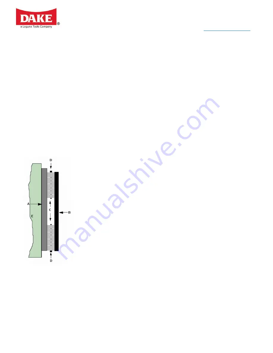
GIB BLOCK ADJUSTMENT
A: Hardened Ways
B: Gib Plate (3 pieces)
C: Gib Blocks (6 pieces)
D: Gib Block Adjusting Bolts
E: Vertical Column
1. Remove rear cover plate from vertical column.
2. Locate the six cast iron gib blocks mounted to the three gib block plates, two located on
the back of the column and the last located on the left side of the column.
3. Tighten the gibs by turning the adjusting bolts clockwise, half a turn at a time to compress
gib blocks.
4. Tighten all blocks equally until the head travels smoothly on the column.
5. To square the cutting head, loosen and tighten block accordingly.
Note: Keep ways oiled.


