background image


 Dake Corporation 

1809 Industrial Park Dr 

Grand Haven, MI 49414 

www.dakecorp.com 


Part# VDL-18 


15 

 REV#082020 

Maintenance  

 Before performing any maintenance to the machine, make sure to unplug the cord from 

the power source before cleaning. 

Maintain bearing guides clean and free of build-up.


Check that the cleaning brush over the band wheel is working properly and remove any 

deposits from the band wheels to avoid vibration and blade breakage. 

The table surface should be always kept clean and free of rust for best results. talcum powder 

applied with a blackboard eraser rubbed in vigorously once a week; this will fill casting pores 

and form a moisture barrier. This method provides a tabletop that is slick and allows rust rings 

to be easily wiped from the surface. 

Clean and grease all mechanical movement components such as gears, bars, if it becomes 

difficult to adjust. 

Clean and oil the tensioning mechanism if it becomes difficult to adjust. 

Check the drive V-belt for cracks overtime. Replace if any irregular wear is present. 


Summary of Contents for Dake VDL-18

Page 1: ...dustrial Park Dr customerservice dakecorp com Grand Haven MI 49417 DAKE VDL 18 INSTRUCTIONAL MANUAL WARNING Read and understand all instructions and responsibilities before operating Failure to follow safety instructions and labels could result in serious injury ...

Page 2: ...ade Installation Steps 11 High to Low Setting FPM setting 12 Blade Speed Chart 13 Blade Guidepost Adjustment 13 Table Tilt 14 Fence Assembly Adjustment 14 Top Idler Wheel Camber Adjustment 14 Maintenance 15 Trouble Shooting 16 Parts List 17 Upper Wheel Assembly Parts List Below 17 Table and Fence Assembly Parts List Below 20 Upper Lower Blade Guides Assembly Parts List Below 23 Lower Wheel Motor A...

Page 3: ...ns to the repair work completed The standard limited warranty includes repair of the defective component part at no cost to the end user Warranty Process Subject to the conditions hereinafter set forth the manufacturer will repair or replace any portion of the product that proves defective in materials or workmanship The manufacturer retains the sole right and option after inspection to determine ...

Page 4: ...r installation or failure to operate or maintain the unit in accordance with the printed instructions provided c Defects or malfunctions resulting from abuse accident neglect or damage outside of prepaid freight terms d Normal maintenance service or preventative maintenance and the parts used in connection with such service e Units and parts which have been altered or repaired other than by the ma...

Page 5: ...pproved by Customer Service a representative will supply a Return Material Authorization RMA number The returned item must have the provided RMA number clearly marked on the outside packaging Any item received without an RMA number clearly visible on the packaging will not be processed An RMA number can only be provided by the Dake Customer Service team and must be obtained prior to the return shi...

Page 6: ... 143 3 4 3 651mm Maximum blade length 145 1 2 3 695mm Maximum blade width 1 1 4 31 75mm Minimum blade width 1 8 3mm Guides Laguna ceramic Blade speeds FPM Variable speeds Low 100 290 High 1200 3500 Dust chute diameter OD 4 x 2 Height 77 3 4 1 975mm Machine dimensions W x D Base footprint 36 3 16 x 36 919mm x 915mm 27 x 19 2 3 688mmx500mm Machine dimensions with mobility kit W x D Base footprint wi...

Page 7: ...18 7 REV 082020 In the space provided record the serial number and model number of the machine This information is only found on the black Dake tag If contacting Dake this information must be provided to assist in identifying the specific machine Model No Part No Serial No Date of Purchase ...

Page 8: ...t incurring obligations Always include the part number model number and parts description for parts orders or correspondence concerning your bandsaw so we can supply you a rapidly after sales service WARNING 1 Read the operator s manual carefully Learn the tools applications and limitations as well as the specific potential hazards peculiar to it 2 Always wear approved safety glasses face shields ...

Page 9: ...a safe distance from the work area 17 Use recommended accessories improper accessories may be hazardous 18 Never place hands directly in line with the saw blade 19 Always use push sticks when cutting small material 20 Raise or lower the blade guide only when the machine has been turned off and the blade has stopped moving 21 Read and understand warnings posted on the machine 22 DO NOT use attachme...

Page 10: ...Dake Corporation 1809 Industrial Park Dr Grand Haven MI 49414 www dakecorp com Part VDL 18 10 REV 082020 Safety Labels Label Part 84605 Label Part 84395 Label Part 84605 Label Part 82199 ...

Page 11: ...injury and maintaining an accurate cut is difficult Blade Installation Steps Disconnect the machine from the power source before making any adjustments 1 Open the top door to the machine Located on the back side of tensioner wheel is 13mm bolt and a nut Loosen to be finger loose You DO NOT need to take the screw all the way out This will save you a headache in the future 2 Lower the tension lever ...

Page 12: ...ne off and unplug from the power source NOTE The motor MUST BE OFF before going to the next step 2 Once the motor is completely off slide the lever to the desired high to low setting You may run into situations where the level does not fully go into low or high If so carefully rotate the blade while trying to put the motor into gear The lever will fully go into to gear Blade Speed Ranges FPM High ...

Page 13: ...et Rod Rounds 3000 Hard Rubber 3000 Plywood 3000 Other Woods 3000 Blade Guidepost Adjustment The following steps are to properly adjust the Blade Guidepost height on the VDL 18 Bandsaw 1 Locate the guidepost locking screw located on the rear top half go the bandsaw To make any adjustments loosen the locking screw to allow the blade guidepost to freely move horizontally 2 The hand wheel located abo...

Page 14: ...d not rub against the table surface but be slightly above it This gap should be the same at the front of the table as it is at the rear 1 Loosen the fence locking wheel located on the fence assembly 2 The fence is now free to move vertically along the worktable 3 Once in the desired spot lock the fence in place by tightening the locking screw Top Idler Wheel Camber Adjustment This adjustment align...

Page 15: ...ibration and blade breakage The table surface should be always kept clean and free of rust for best results talcum powder applied with a blackboard eraser rubbed in vigorously once a week this will fill casting pores and form a moisture barrier This method provides a tabletop that is slick and allows rust rings to be easily wiped from the surface Clean and grease all mechanical movement components...

Page 16: ...el replace if necessary Lower Drive Wheel Check bearing area for leakage of lubricant Monthly Replace bearing if leakage occurs Upper Drive Wheel Check bearing area for leakage of lubrication Monthly Replace bearing if leakage occurs Drive Wheel Rubber Tires Check for cleanliness Daily and when changing blade Wipe or brush clean Drive Belt Check for smooth surfaces and adherence to drive wheel Che...

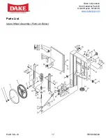
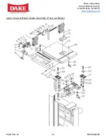
Page 17: ...Dake Corporation 1809 Industrial Park Dr Grand Haven MI 49414 www dakecorp com Part VDL 18 17 REV 082020 Parts List Upper Wheel Assembly Parts List Below ...

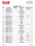
Page 18: ...3 15 Pointer 1 16 PBAND18BX2203 16 Special Bolt 2 17 PBAND18BX2203 17 Spring 1 18 PBAND18BX2203 18 Bracket 1 19 PBAND1412 175 19 Pin Ø4x20 1 20 PBAND18BX2203 20 Adjusting Screw 1 21 PBAND18BX2203 21 Blade Tension Arm Assembly 1 22 PBAND18BX2203 22 Support Block 1 23 PBAND1412 175 23 Plate 1 24 PBAND1412 175 24 Handle 1 25 PBAND1412 175 25 Door Hinge Set 2 25 1 PBAND1412 175 25 1 Door Hinge Left 2 ...

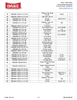
Page 19: ...ND1412 175 48 Lock Knob 1 49 PBAND1412 175 49 Adjusting Knob 1 50 PBAND1412 175 50 Tension Label 1 51 PBAND18BX2203 51 Upper Door 1 52 PBAND18CX110175 52 Logo Label 1 53 PBAND1412 175 53 Hinge Cover 1 54 MBAND14BX110 175 54 Emergency Stop 1 55 PBAND1412 175 55 Warning Label 1 56 PBAND1412 175 2 13 Lock Washer 5 16 7 57 PBAND1412 175 2 11 Flat Washer 5 16 8 58 PBAND1412 175 3 38 Hex Nut 5 16 18 6 5...

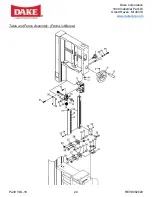
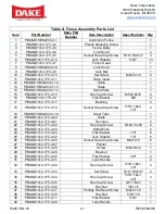
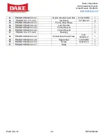
Page 20: ...Dake Corporation 1809 Industrial Park Dr Grand Haven MI 49414 www dakecorp com Part VDL 18 20 REV 082020 Table and Fence Assembly Parts List Below ...

Page 21: ... M5 2 17 PBAND1412 175 3 17 Bushing 2 18 PBAND1412 175 3 18 Socket Head Cap Screw 5 16 18x2 1 2 2 19 PBAND18BX2203 3 19 Steel Tube 1 20 PBAND1412 175 3 20 Scale 1 21 PBAND1412 175 3 21 Trunnion 2 22 PBAND1412 175 3 22 Hex Cap Screw M10x1 5x50 2 23 PBAND1412 175 3 23 Slide Block 2 24 PBAND1412 175 3 24 Flat Washer 1 4 6 25 PBAND1412 175 2 42 Lock Washer 1 4 6 26 PBAND1412 175 3 26 Socket Head Cap S...

Page 22: ...3 42 Set Screw 1 4 20x1 4 2 43 PBAND18BX2203 3 43 Fence Stop Hinge 1 44 PBAND18BX2203 3 44 Lock Handle 1 45 PBAND18BX2203 3 45 Fence Stop A 1 46 PBAND18BX2203 3 46 Fence Stop B 1 47 PBAND1412 175 6 26 Bushing 2 48 PBAND18BX2203 3 48 Socket Head Cap Screw 5 16 18UNCx2 1 49 PBAND18BX2203 3 49 Square Nut 1 4 20UNC 1 50 PBAND18BX2203 3 50 Screw M3x0 5x4 2 51 PBAND18BX2203 3 51 Scale 1 ...

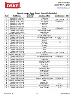
Page 23: ...Dake Corporation 1809 Industrial Park Dr Grand Haven MI 49414 www dakecorp com Part VDL 18 23 REV 082020 Upper Lower Blade Guides Assembly Parts List Below ...

Page 24: ...75 4 16 Gear Base 1 17 PBAND1412 175 4 17 Bushing 1 18 PBAND1412 175 4 18 Shaft 1 19 PBAND1412 175 4 19 Gear 1 20 PBAND1412 175 4 20 Plate 1 21 PBAND1412 175 4 21 Socket Head Button Screw 5 16 18x1 2 4 22 PBAND18BX2203 4 22 Guide Bar 1 23 PBAND1412 175 4 23 Socket Head Cap Screw 1 4 20x5 8 4 24 PBAND1412 175 42 Lock Washer 1 4 2 25 PBAND1412 175 4 25 Lock Knob 4 26 PBAND1412 175 4 26 Ceramic Guide...

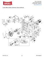
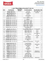
Page 25: ...Dake Corporation 1809 Industrial Park Dr Grand Haven MI 49414 www dakecorp com Part VDL 18 25 REV 082020 Lower Wheel Motor Assembly Parts List Below ...

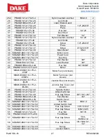
Page 26: ...Set Screw 5 16 18x3 8 4 7I PBAND18CX110175 2 7I Motor Pulley Pin 6x16 2 7J PBAND18CX110175 2 7J Motor Pulley Pin 5x10 1 7K PBAND18CX110175 2 7k Motor Pulley Pin 6x12 2 8 PBAND18CX110175 2 8 Hex Cap Screw 3 8 16UNCx1 3 4 1 9 PBAND18CX110175 2 9 Key 7x7x100 1 10 MBAND14BX110 175 2 10 Flat Washer 1 4 2 76 PBAND1412 175 2 11 Flat Washer 5 16 2 12 PBAND18CX110175 2 12 Spindle Pulley 1 13 MBAND14BX110 1...

Page 27: ...at Washer 3 8 7 43 PBAND1412 175 8 Lock Washer 3 8 5 44 PBAND18BX2203 2 44 Hex Nut 3 4 16UNF 1 45 PBAND18CX110175 2 45 Motor 1 MBAND14BX110 175 2 45MF Motor Fan not shown 1 MBAND14BX110 175 2 45MFC Motor Fan Cover not shown 1 MBAND14BX110 175 2 45JB Junction Box not shown 1 MBAND14BX110 175 2 45JBC Junction Box Cover not shown 1 46 PBAND1412 175 2 46 Spindle Holder 1 47 PBAND1412 175 2 47 Adjustin...

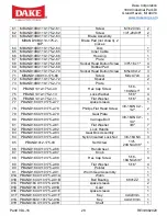
Page 28: ... Flat Washer 5 16 4 77 PBAND18CX110175 2 77 spacer sleeve 1 78 PBAND18CX110175 2 78 Phillips Flat Head Screw 3 8 16UNCx1 1 2 2 79 PBAND18CX110175 2 79 Gear Plate 1 80 PBAND18CX110175 2 80 Carriage Bolt 3 8 16UNCx1 1 4 1 81 PBAND18CX110175 2 81 Flat Washer 3 8 7 82 PBAND18CX110175 2 82 Lock Handle 1 83 PBAND18CX110175 2 83 Gear Box Assembly 1 84 PBAND18CX110175 2 84 Nylon Inserted Lock Nut 3 8 16UN...

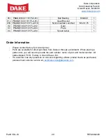
Page 29: ...D18CX110175 2 93 Plate 1 94 PBAND18CX110175 2 94 Speed Label 1 Order Information Please contact factory for current prices Parts are available for direct purchase from Dake or through a distributor When placing a parts order you will need to provide the part number name of part and model number All parts shipped F O B Factory in Grand Haven MI If a customer has any questions or concerns regarding ...

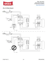
Page 30: ...Dake Corporation 1809 Industrial Park Dr Grand Haven MI 49414 www dakecorp com Part VDL 18 30 REV 082020 VDL 18 Wiring Diagram ...

Reviews: