14
2. Setup
CO2 Laser Machine © 2018 Laguna Tools 8/27/2018
2.
S
et
up
EN
Installing the Laser Tube
Note: Although only the MX machine is shown, this section is similar for all Laguna
laser machines.
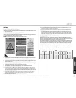
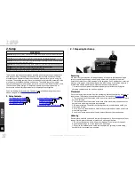
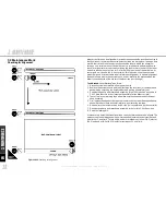
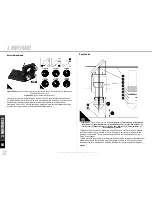
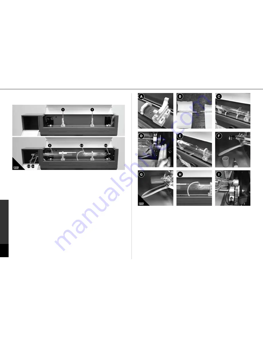
Figure C028: Laser Tube Installation. (1)
Laser Tube mount.
(2)
Laser Tube.
(2.1)
Water
Outlet.
(2.2)
Anode Terminal.
(2.3)
Cathode Terminal.
(2.4)
Water Inlet.
The laser tube must be shipped in a separate insulated package to prevent damage
upon shipment. In our quality and testing facility, the tube is mounted and the laser
machine mirrors are aligned accordingly. The laser tube is then removed and put
back in the original packaging.
Because of this, it should not be necessary to re-
align the mirrors.
To reinstall the laser tube, follow the procedure exactly. Avoid any
adjustments to mirrors or laser tube mounts during the installation.
Tools Needed:
Allan Wrenches. Phillips head screwdriver (short)
DANGER
Make absolutely sure that the machine is not connected to the power
source.
A. Remove the top portion of each (1) laser tube mount with an allen wrench. Do
not make any adjustments to the other components of the laser tube mounts.
B. Carefully remove the (2) laser tube from the packaging.
C. Carefully place the (2) laser tube in the laser tube mounts. Once in place, rotate
the laser tube so that the (2.1) water outlet tube is pointed straight up. This will
eliminate any air bubbles form staying stagnate in the laser tube.
D. Position the laser tube by translating the position of the laser tube to a distance
of 1.5-2" form the first mirror assembly. A width of 2 fingers is adequate.
E. Reinstalled the top mounts of the (1) laser tube mounts. Only tighten down
enough to secure the tube - DO NOT over-tighten. DO NOT adjust the height or
position of the tube mounts at this time.
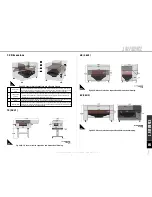
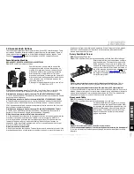
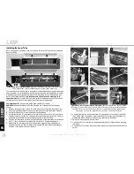
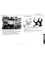
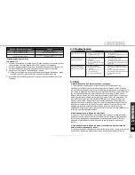
Figure C031: Laser Tube Installation Procedures. (A)
Laser tube Mount. (B) Laser tube
packaging. (C) Laser tube in place, rotate water outlet vertical. (D) Laser tube two finger
spacing from mirror. (E) Laser tube mounted. (F) Cathode Connection & Water Inlet
Connection. (G) Cap. (H) Water Outlet Connection. (I) Anode Connection
F. Unscrew the red cap and connect the (2.3) cathode wire to the laser tube with
the Phillips head connection screw. Install the (2.4) water inlet connection by
wetting the tube with water and pushing it completely into place.
G. Screw the red safety cap back in place.
H. Connect the (2.1) water outlet tube by wetting the end of the tube and pushing
into place.
I. Connect the (2.2) anode wire to the laser tube with the phillips head connection
screw.


