19
13. Blade-tracking knob.
The blade-tracking knob is located at the back of the bandsaw and is used to adjust the blade
tracking. The knob must be locked once the adjustment is completed.
14.
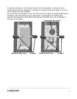
Optional mobility kit. Swivel wheel assembly
The optional mobility kit is fitted to the base of the
bandsaw and consists of two fixed wheels at the
front of the bandsaw and a swivel wheel at the back
of the band saw. The swivel wheel is activated and
deactivated with a foot lever. With the swivel wheel
deactivated, the bandsaw sits on two rubber feet.
15.
Optional light.
The optional light is fitted with four screws through
pre-drilled holes at the top of the bandsaw. The
bandsaw is provided with a 220V socket that the
light can be connected to.
16.
Blade guide shaft lock
knob.
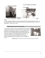
The upper blade guide is fixed to the blade guide
Rubber feet
shaft, which is vertically adjustable. Once the guides have been adjusted vertically,
the shaft is locked in position with the lock knob.
17.
Flywheel.
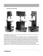
The blade is suspended over two wheels that are covered with rubber called a "tire". The tire
cushions the blade and protects the teeth from meeting the metal of the flywheel. The lower
wheel is the drive wheel and is attached to the motor with a rubber drive belt. The lower
flywheel powers the blade and pulls the blade down through the work piece. The top wheel
has two functions. One function is to balance or track the blade on the wheels, and the
second one is to tension the blade. Both functions are adjustable.
Summary of Contents for MBAND18BX2203
Page 3: ...3 Laguna Tools MBAND18BX2203 Bandsaw User Manual Safety Rules...
Page 4: ...4...
Page 10: ...10 Industrial work light Optional Fence Face Dimensions 7 1 4 x 2 2 3 4...
Page 14: ...14 Fence parts Fence guide bar Fence stop...
Page 51: ...51 Step 1 Step 2 Step 3 Step 4 Done Maintenance...
Page 59: ...59...
Page 60: ...60 LT18BX MBAND18BX2203 220V wiring diagram...
Page 68: ...68...
Page 71: ...71...
Page 74: ......
Page 76: ......

