23
Setting the work envelope
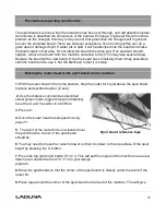
The Work Envelope is a volume that defines the movement
limits of the router spindle. The X0, Y0 corner of the work
envelope is determined by the machine’s Home Position.
The X+ and Y+ limits of the work envelope are determined
by the “Table Size: Settings (MENU/MACHINE
SETUP/TABLE
SIZE) and provide the “soft limits” for the
machine. The Table Size settings prevent the possibility of
the spindle assembly/gantry from being jogged into the
machine’s frame.
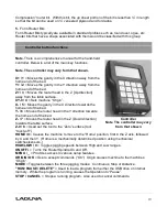
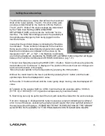
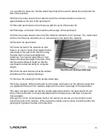
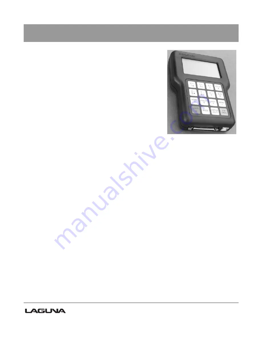
Insure that the controller display is indicating the “Machine
Coordinates”. T
hose numbers correspond to the machine
Home position that is determined by physical limit switches.
Machine Coordinates are indicated on the screen by the
designation “AX
"", AY", or "AZ". I the Machine Coordinates
are not being displayed, depressing the HIGH/LOW and MENU buttons together will toggle
between the machine coordinates and ORIGIN coordinates. (e.g. 1-9.)
1.
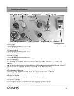
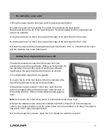
Select Low Speed by pressing the HIGH LOW / 0 button. Select Continuous by press the
mode button until “Continuous” is displayed.
The position of the router head as it changes will
be shown at the bottom of the display.
Move the router spindle to the home position by pressing the Home button.
2.
Move the router head to the max X position by pressing the X+ button until the router
spindle stops. Note the displayed AX= value.
3.
Press the Y+ button and hold until the router gantry stops moving, note the displayed AY
value.
.
4.
Typically on the Laguna Swift 4 x 4 CNC machine the work envelope will be 1300mm
[51.181 in] x 1300mm [51.181 in] (work envelopes vary by machine model).
5.
Machining can only be performed if the tool path centerlines fall within the work envelope.
If an error message is displayed while trying to execute a program indicating an oveltravel
error in one of the Axes, executing the program would require that a tool path fall outside of
the machine’s Work Envelope. PLEASE NOTE THAT THE SELECTION OF THE “ORIGIN”
ALSO EFFECTS PLACEMENT OF THE PROGRAM WITHIN THE WORK ENVELOPE.
Summary of Contents for MCNC Swift 60 X 120-0233
Page 2: ......
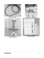
Page 11: ...11 Spare drive belts Dust hood Wrenches Table clamps qty 8 Coolant container...
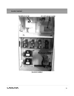
Page 30: ...30 Control cabinet Spindle inverter 24 volt power supply Control cabinet...
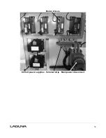
Page 32: ...32 Motor drivers 80 Volt power supplies Terminal strip Main power disconnect...
Page 35: ...35 1 Machine not level on the floor Re level the machine ensuring that it has no movement...

