6
Changing Units of Measure
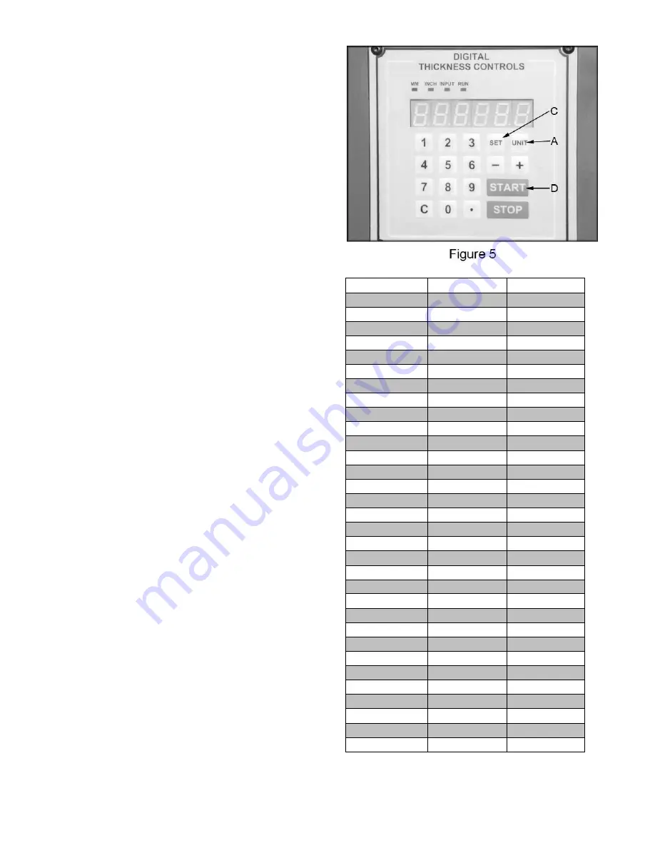
Press unit button A (Fig. 5) to toggle back and
forth between inches and millimeters.
Calibrating the Display
The following sections will describe the use
of a calibrating board. The calibrating
board should be made of a hardwood and
have one side that has been run through a
jointer.
1. With the planer turned “OFF – cutterhead
NOT spinning”, place your calibrating
board jointed surface down on the table
and slide it into the machine.
2. Use the table “UP” button to raise the
table so that the in-feed roller is about
1/32" above the calibrating board.
3. Remove calibrating board from planer and
turn the planer “ON”.
4. Use the table “UP” button to raise the
table about 0.1", as indicated by LED
and run the calibrating board through the
planer.
5. Repeat Step 4 until the planer removes
the entire top surface of your calibrating
board.
6. Measure the thickness of the board using
a pair of calipers.
7. Press the “SET” button C (Fig.5) and
then type in the measured thickness from
step 6. Press the “SET” button again and
hold in until the decimal point stops
blinking (about three seconds).
Planning to a Specific Thickness
1. Measure thickest section of the workpiece.
2. Subtract the amount you wish to remove
from the current thickness of the
workpiece.
3. Press the “SET” button and enter the
amount from step 2.
4. Press “START” button D (Fig. 5) to begin
the table movement up, or down until the
set value is achieved.
Note: Do not feed material through the
planer while the table is raising or
lowering.
Fraction
Decimal
Metric
1/32
0.031
0.794
1/16
0.063
1.588
3/32
0.094
2.381
1/8
0.125
3.175
5/32
0.156
3.969
3/16
0.188
4.763
7/32
0.219
5.556
1/4
0.250
6.350
9/32
0.281
7.144
5/16
0.313
7.938
11/32
0.344
8.731
3/8
0.375
9.525
13/32
0.406
10.319
7/16
0.438
11.113
15/32
0.469
11.906
1/2
0.500
12.700
17/32
0.531
13.494
9/16
0.563
14.288
19/32
0.594
15.081
5/8
0.625
15.875
21/32
0.656
16.669
11/16
0.688
17.463
23/32
0.719
18.256
3/4
0.750
19.050
25/32
0.781
19.844
13/16
0.813
20.638
27/32
0.844
21.431
7/8
0.875
22.225
29/32
0.906
23.019
15/16
0.938
23.813
31/32
0.969
24.606
1
1.00
25.400
Figure 6
Summary of Contents for MPLAN25-10-1-0130
Page 17: ...16 PARTS DIAGRAMS...
Page 18: ...17...
Page 19: ...18...
Page 20: ...19...
Page 21: ...20...


