3. ASSEMBLY & SETUP
10
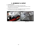
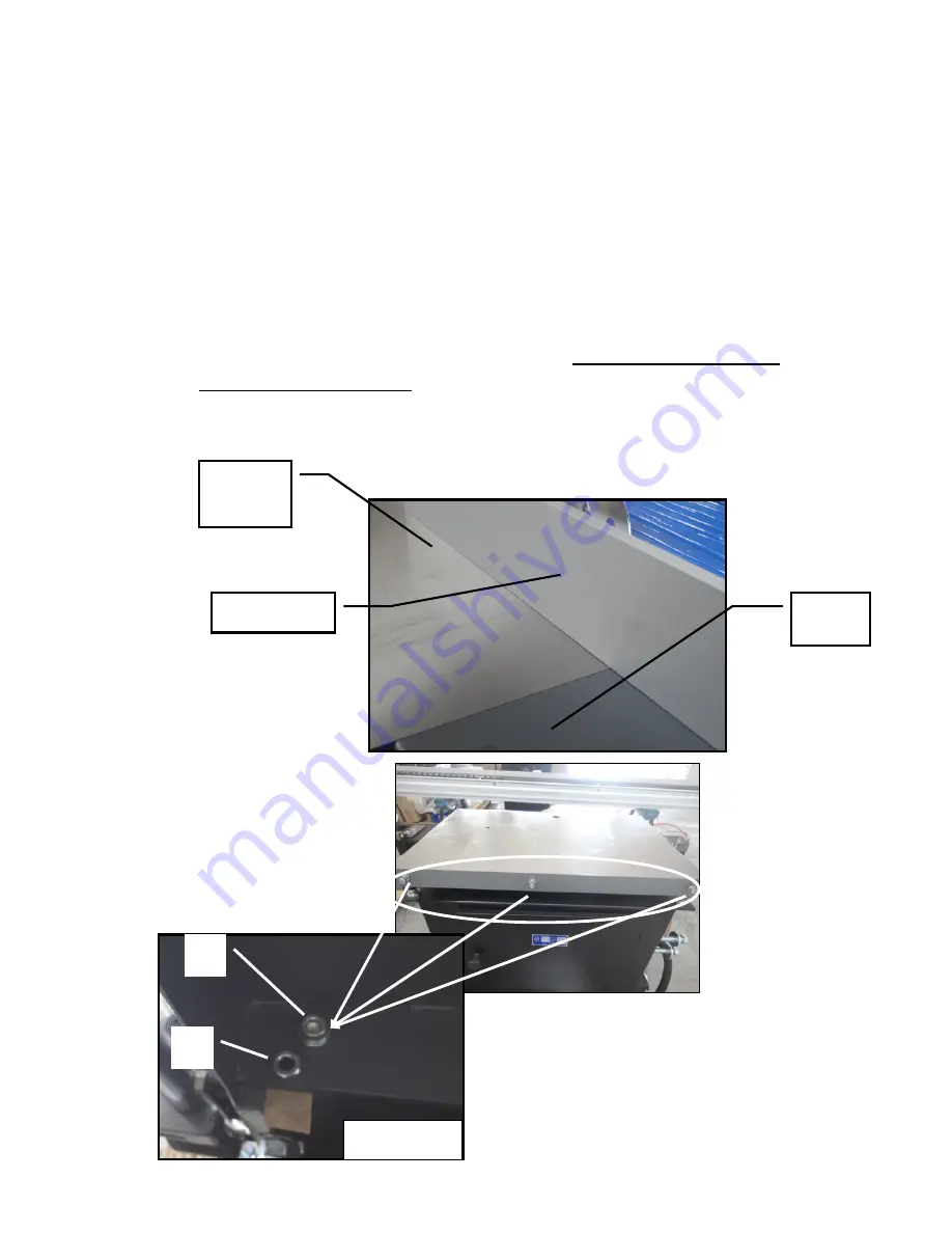
3-3 EXTENSION TABLE
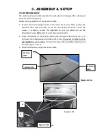
The machine extension table prevents the work piece from tipping after cutting and
increases the working safety.
Follow the steps below to fit the extension table:
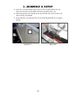
1. Remove the screws
A
(Fig.3-3.1) from the side of the cast iron table, position the
extension table over the holes on the cast iron table and secure it with the
screws. If necessary, correct the alignment to cast iron table and use the
adjustment screws
B (
Fig 3-3.1b) under the extension table.
2. Check the flatness of the table by placing the fence plate
E
(see Fig. 3-4.1) on
both cast iron table & extension table as Fig. 3-3.1a. The extension table must be
even height
to cast iron table. If it has to be lower, the acceptable distance must
less than approx. 0.2mm.
3. Adjust the screws to support extension table.
Figure 3-3.1
Figure 3-3.1a
Fence plate
Cast iron
table
Extension
table
Figure 3-3.1b
A
B
Summary of Contents for MTST5S-0135
Page 3: ......
Page 36: ......
Page 37: ...MTST5S 0135 ASSEM1 1 5 1...
Page 39: ...MTST5S 0135 ASSEM1 3 3 3...
Page 42: ...MTS5S 0135 ASSEM3 1 1 6...
Page 44: ...MTST5S 0135 ASSEM3 3 8...
Page 46: ...MTST5S 0135 ASSEM3 4 2 10...
Page 48: ...MTST5S 0135 ASSEM 4 1 12...
Page 50: ...MTST5S 0135 ASSEM5 2 14...
Page 52: ...MTST5S 0135 ASSEM6 2 16...
Page 54: ...MTST5S 0135 ASSEM6 4 18...
Page 56: ...MTST5S 0135 ASSEM10 1 20...


