3. ASSEMBLY & SETUP
11
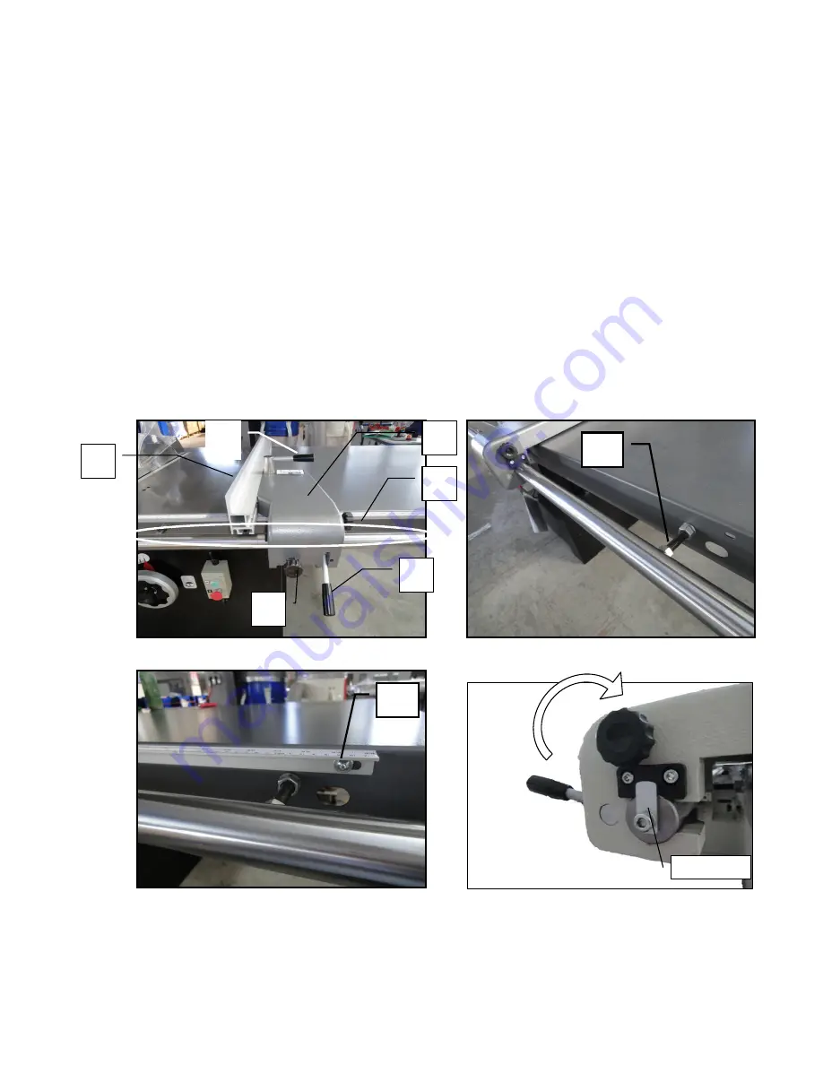
3-4 RIP FENCE
1.
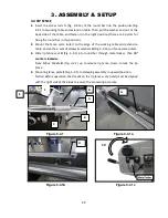
Insert the screw rods G (Fig. 3-4.1a) of the round bar into the position
A
(Fig.
3-4.1) of working table and extension table. Then put the washer and nut at the
back side of the table, and fasten it in the right position (there are 4 points for
fixing the round bar in this position).
2.
Mount the fence scale (ruler) to the edge of the working table and extension
table. Fasten the 3 sets of screws & washers
H
(Fig. 3-4.1b) on fence scale (ruler).
3.
Slide rip fence seat
D
(Fig. 3-4.1) into round bar through metal locker, then 9
0°
counter clockwise
Note: Move handle
B
(Fig. 3-4.1) up to release rip fence, down to lock the rip
fence.
4.
Mounting fence plate
E
(Fig. 3-4.1) to clamping assembly in upward position.
Notice: Before operation, the 0 mark on the rip fence scale (ruler) must be aligned
with the right side of the blade to ensure the processing accurate.
Figure 3-4.1a
G
Figure 3-4.1b
H
Figure 3-4.1c
I
Figure 3-4.1
A
B
D
E
F
C
90°
Metal locker
Summary of Contents for MTST5S-0135
Page 3: ......
Page 36: ......
Page 37: ...MTST5S 0135 ASSEM1 1 5 1...
Page 39: ...MTST5S 0135 ASSEM1 3 3 3...
Page 42: ...MTS5S 0135 ASSEM3 1 1 6...
Page 44: ...MTST5S 0135 ASSEM3 3 8...
Page 46: ...MTST5S 0135 ASSEM3 4 2 10...
Page 48: ...MTST5S 0135 ASSEM 4 1 12...
Page 50: ...MTST5S 0135 ASSEM5 2 14...
Page 52: ...MTST5S 0135 ASSEM6 2 16...
Page 54: ...MTST5S 0135 ASSEM6 4 18...
Page 56: ...MTST5S 0135 ASSEM10 1 20...


