3. INSTALLATION
11
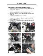
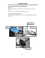
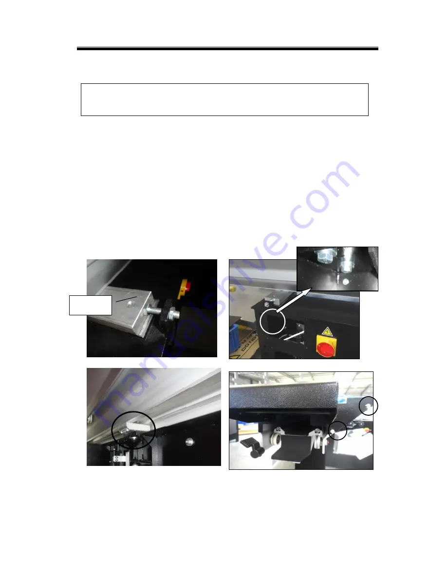
3-3.FITTING THE SLIDING TABLE
The accessories bag contains hex head bolts for fixing the sliding table
Note: The parallelism has been adjusted before shipping, users only need to
assemble by following the steps below. Then the position of sliding table will be
correct.
1.
Put the sliding table on the machine frame
2.
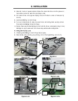
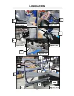
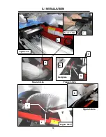
Position the fix blocks on 2 sides set points as Fig. 3-3.1a
3.
Lock the screws (2 sets on each side) on 2 sides to fix the sliding table on the
machine frame. (Fig. 3-3.1b)
4.
Lock the middle fix block of sliding table on the machine frame. (Fig. 3-3.1c)
5.
To assemble for the handle of sliding table, fit the screws in as Fig. 3-3.2 shows.
For packing and transport reasons, some machine members are removed.
All fitting operations in this section require approx. 4 people
Figure 3-3.2
Figure 3-3.1a
Figure 3-3.1b
Fix block
Figure 3-3.1c
Summary of Contents for P12 10
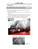
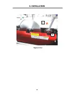
Page 26: ...3 INSTALLATION 22 Figure 3 10 2 D C ...
Page 52: ......
Page 53: ......
Page 54: ...MPSP12 10 0135 ASSEM 1 1 23 1 ...
Page 58: ...MPSP12 10 0135 ASSEM 1 2 4 5 ...
Page 60: ...MPSP12 10 0135 ASSEM 3 1 5 7 ...
Page 63: ...MPSP12 10 0135 ASSEM 3 2 6 10 ...
Page 65: ...MPSP12 10 0135 ASSEM 3 3 5 12 ...
Page 67: ...MPSP12 10 0135 ASSEM 4 10 14 ...
Page 69: ...MPSP12 10 0135 ASSEM 5 7 16 ...
Page 72: ...MPSP12 10 0135 ASSEM 6 1 19 ...
Page 74: ...MPSP12 10 0135 ASSEM 6 2 21 ...
Page 76: ...MPSP12 10 0135 ASSEM 6 3 23 ...
Page 78: ...MPSP12 10 0135 ASSEM 7 6 3200mm 25 ...
Page 80: ...MPSP12 10 0135 ASSEM 8 1 27 ...
Page 82: ...MPSP12 10 0135 ASSEM 9 3 29 ...
Page 85: ...MPSP12 10 0135 ASSEM 10 3 32 ...
Page 89: ...MPSP12 10 0135 ASSEM 12 6 4 36 ...
Page 92: ...MPSP12 10 0135 ASSEM 12 10 39 ...


