background image


14 


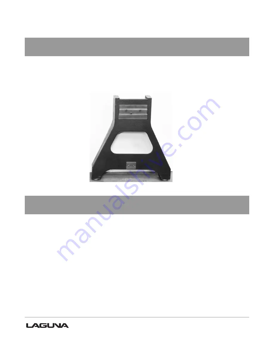
Lathe legs. 


The Legs are cast iron, and their heavy construction gives the machine a low center of gravity 

and ensures that it is very stable. The legs are supplied with adjustable feet to allow the 

machine to be leveled. 


Legs with adjustable feet assembled 


Head stock. 


The head stock is cast iron and houses the variable speed control and motor. The  

Spindle can be locked in 14 / 36 and  48 positions. 


Summary of Contents for REVO 24-36

Page 1: ...1 Original Instructions...

Page 2: ...General principles for design Risk Assessment and Risk reduction EN 60204 1 2006 AC 2010 Safety of machinery Electrical equipment of machines part 1 General requirements EN 13849 1 2015 Safety of mach...

Page 3: ...100 2010 Safety of Machinery General principles for design Risk Assessment and Risk reduction EN 60204 1 2018 Safety of machinery Electrical equipment of machines part 1 General requirements EN 13849...

Page 4: ...et 10 Receiving your machine 11 Introduction to your machine 12 Parts of the machine 12 What you will receive with the machine 17 Where to locate your machine 20 Unpacking your machine 20 Assembly and...

Page 5: ...ds to operate tool 13 DON T OVERREACH Keep proper footing and balance at all times 14 MAINTAIN TOOLS WITH CARE Keep tools sharp and clean for best and safest performance Fol low instructions for lubri...

Page 6: ...5 Location of warning signs...

Page 7: ...iture legs lamp posts baseball bats bowls and other ornamental forms Wood lathe tooling consists of fixturing and securing devices for the work piece a moveable tool rest and hand held cutting tools i...

Page 8: ...re made to lock the control panels on both headstock and remote controller We have supplied four concepts for locking the control panel see below First push down the emergency stop Then lock the cover...

Page 9: ...hers Laguna Tools Inc is not responsible for additional tools or modifications sold or performed other than from by Laguna Tools Inc on any Laguna Tools Inc woodworking machine Warranty may be voided...

Page 10: ...and exposure levels this cannot be used reliably to determine whether or not further precautions are required Factors that influence the actual level of exposure of the workforce include characteristi...

Page 11: ...4mm 660mm 1327mm Tool rest 12 305mm Speed range high 135 3500 RPM Speed range low 50 1300 RPM VFD Delta variable frequency drive Drive belt Poly groove drive belt with easy access Spindle M33 x 3 5 ri...

Page 12: ...n contact the seller Laguna Tools as soon as practical If damage is found after delivery contact the seller as soon as is practical Note It is probable that you will find sawdust within your machine T...

Page 13: ...its entirety before assembly or use Parts of the lathe The lathe consists of a number of major parts which are discussed in this manual Take the time to read this section and become familiar with the...

Page 14: ...The bed is a machined heavy steel welded construction Underside of lathe bed Model REVO 24 36 Power 1 230V 50Hz 9A P2 2 2kw S1 Specification n0 0 3500 min SCCR 6k A M33x3 5 MT 2 10 5mm Article No LAGU...

Page 15: ...f gravity and ensures that it is very stable The legs are supplied with adjustable feet to allow the machine to be leveled Legs with adjustable feet assembled Head stock The head stock is cast iron an...

Page 16: ...a number 2 Morse Taper The tail stock can be moved to any position on the lathe bed and locked to suit the job at hand Tool rest The tool rest can be moved to any position on the lathe bed and locked...

Page 17: ...erts single phase 220v to three phase There is a speed readout at the front of the lathe with controls to fine adjust the RPM of the spindle A power cord with 220V plug is provided There are two elect...

Page 18: ...17 Tool storage A tool storage bracket which can be mounted on either leg What you will receive with the lathe Tool storage bracket...

Page 19: ...18 Head stock Tool rest Tail stock Drive live center storage Tool storage Leg Bed Banjo Adjustable feet Leg Remote controller Face plate Tool rack Rotating center Adjustable feet Tail stock bracket...

Page 20: ...19 Removal tool Drive center Knock out rod Head stock bracket Tail stock knob Tool rest comes fitted to banjo Remote brackets and hardware...

Page 21: ...3 Adequate lighting The better the lighting the more accurately and safely you will be able to work 4 Solid floor You should select a solid flat floor preferably one made of concrete or something sim...

Page 22: ...athe bed It is recommended that it be lifted with a hoist or forklift using a sling as it is very heavy Note The machine is heavy Ensure that you have enough people to do the job safely Note If you ha...

Page 23: ...ends of the bed The stop is a safety feature that makes it impossible for the headstock or tailstock to slide off the end of the bed Remove the stops and loosen the clamps on both the head stock tool...

Page 24: ...ot attempt any procedure that you feel is unsafe or that you do not have the physical capability of achieving Fit the 4 leveling feet to the lathe legs with the lock nut on the underside of the leg On...

Page 25: ...the tool rest onto the bed of the lathe ensuring that the washer recess fits into the slot in the bed Fit the banjo onto the bed with the bolt through the washer and assemble the nut onto the thread...

Page 26: ...knob onto the tail stock handle Connecting the electrical supply Ensure that the electrical supply corresponds with that of the machine Single phase 220V It is recommended that you use a 15 amp main b...

Page 27: ...by removing the two clamp bolts and with the two clamp screws secure the support plate 2 Fit the remote controller with the clamping supplied screws 3 Ensure that the cable is clear of any obstruction...

Page 28: ...ting with the controller selection switch Cleaning the machine Remove the rust protection grease with WD 40 or a similar solvent It is important that you remove all the grease and re lubricate with a...

Page 29: ...damage the lathe spindle To remove the face plate from the head stock spindle insert the removal tool into the hole in the face plate large diameter Lock the spindle with the lathe spindle lock and un...

Page 30: ...e forward reverse switch selects the direction of the rotation of the spindle The forward reverse switch must only be used once the spindle has come to a complete stop Start Stop buttons The start sto...

Page 31: ...llows the head stock to be released and moved to any position on the lathe bed It is located at the back of the head stock Emergency stop button Start stop buttons Speed display Forward reverse switch...

Page 32: ...as follows 1 Disconnect the electric supply to the lathe 2 Open the pulley cover 3 Loosen the motor lock handle and lift the motor to the highest position with the motor adjustment handle then lock t...

Page 33: ...obs Try the plunger in a few different holes to check that it inserts and removes smoothly The indexing plunger is spring loaded and this is used only to temporarily align the plunger in the selected...

Page 34: ...33 Indexing holes Clamping knobs Hole selection indicator Hole selection Indexing plunger Indexing plunger engaged Indexing plunger disengaged...

Page 35: ...none painted surfaces will rust if not protected It is recommended that they be protected by applying wax or a Teflon based lubricant to them Center point alignment and slide clearance adjustment The...

Page 36: ...s above should be conducted on the head stock should it be required Note It is very unlikely that the headstock will require adjustment as it is not moved as often as the tailstock so has less tendenc...

Page 37: ...points aligned Note It is recommended that the head stock be adjusted and not the tail stock If the tail stock is not adjusted parallel to the bed slide the center point will not be in alignment when...

Page 38: ...urn the spindle by hand If the spindle will not turn check the reason for jamming 2 Capacitor faulty Replace the capacitor 3 Motor faulty Replace the motor 4 Power line overloaded Correct overloaded c...

Page 39: ...floor Re level the machine ensuring that it has no movement 2 Damaged drive belt Replace the belt 3 Job is not balanced Change to slower speed and or balance the job 4 Damaged pulley Replace the pull...

Page 40: ...39 Electrical drawing Manufacturer Laguna Tools Inc Product Name Wood Lathe Model REVO 24 36 Version 2022 01 Drawing Originator Ting Checker Ting Authorizes Alan Huang File no LAGUNA L 0016...

Page 41: ...g diagram for control panel on headstock Manufacturer Laguna Tools Inc Product Name Wood Lathe Model REVO 24 36 Version 2022 01 Drawing Originator Ting Checker Ting Authorizes Alan Huang File no LAGUN...

Page 42: ...Wiring diagram for remote control Manufacturer Laguna Tools Inc Product Name Wood Lathe Model REVO 24 36 Version 2022 01 Drawing Originator Ting Checker Ting Authorizes Alan Huang File no LAGUNA L 00...

Page 43: ...42 Exploded view drawings and parts list...

Page 44: ...ecification Qty 1 PLAREVO1836 101 Bed 1 2 PLAREVO1836 102 Spindle Pulley 1 3 PLAREVO1836 103 Spring 1 4 PLAREVO1836 104 Spindle Lock Plunger 1 5 PLAREVO1836 105 Locking Collar 1 6 PLAREVO1836 106 Bear...

Page 45: ...1836 124 Spur Center 1 25 PLAREVO1836 125 UK Spindle 1 26 PLAREVO1836 126 Index Stud 1 27 PLAREVO1836 127 Index Shaft 1 28 PLAREVO1836 128 Index Bracket 1 29 PLAREVO1836 129 Spring 1 30 PLAREVO1836 13...

Page 46: ...PLAREVO2436 220 163 UK Inverter 1 64 PLAREVO1836 164 Braking Resistor 1 65 PLAREVO1836 165 Screw M4x12 1 66 PLAREVO1836 166 Digital Readout 1 67 PLAREVO1836 167 Digital Readout Sensor 1 68 PLAREVO1836...

Page 47: ...00 Set Screw M4x4 2 101 PLAREVO1836 1101 Set Screw 1 4 20UNCx1 4 4 102 PLAREVO1836 1102 Key 5x5x50 1 103 PLAREVO1836 1103 1 Screw M4x8 16 104 PLAREVO1836 1104 Screw M3x8 6 105 PLAREVO1836 1105 Socket...

Page 48: ...VO1836 1136 Handle Faceplate 1 137 PLAREVO2436 220 1137 Logo Plate 1 138 PLAREVO1836 1138 Strain Relief 6N 4 2 139 PLAREVO1836 1139 Bracket 1 140 PLAREVO1836 1140 Thimble 1 141 PLAREVO1836 1141 Socket...

Page 49: ...W 2 172 PLAREVO2436 220 1172 Rubber Sleeve 1 173 PLAREVO2436 220 1173 Cap 1 174 PLAREVO2436 220 1174 UK Connector Remote 1 175 PLAREVO2436 220 1175 UK Connector Head 1 176 PLAREVO1216 192 Hex Nut 10 3...

Page 50: ...al Headstock Guard Index Part Number Item Description Specification Qty 1 PLAREVO1836 201 Plunger 1 2 PLAREVO1836 202 Retaining Collar 2 3 PLAREVO2436 203 Guard 1 4 PLAREVO1836 1125 Set Screw 5 16 18U...

Page 51: ...50...

Page 52: ...19 Clamp 1 8 PLAREVO1836 114 Clamp Bolt 1 9 PLAREVO1836 115 Sleeve 1 10 PLAREVO1836 116 Rubber Sleeve 1 11 PLAREVO1836 1145 Cap 1 12 PLAREVO1836 189 E Ring E15 4 13 PLAREVO1836 185 Key 6x6x30mm 1 14 P...

Page 53: ...tension 1 2 PLAREVO1836 402 Draw Latch Assembly 1 3 PLAREVO1836 403 Hinge 1 4 PLAREVO1836 404 Pin 2 6 PLAREVO1836 406 Socket Head Cap Screw M6x1 0x12mm 4 7 PLAREVO1836 407 Phillips Flat Head Screw M5x...

Page 54: ...53 Optional Comparator Index Part Number Item Description Specification Qty 1 PLAREVO1836 501 Center 2 2 PLAREVO1836 502 Lock Handle 2...

Page 55: ...54 Optional Industrial Flood Light Index Part Number Item Description Specification Qty 1 PLAREVO1836 601 Work Light 1 2 PLAREVO1836 602 Screw M4x0 7x20mm 4...

Page 56: ...55...

Page 57: ...e Fitting 1 14 PLAREVO1836 814 Pressure Vacuum Gauge 1 15 PLAREVO1836 815 Gauge Fitting 1 16 PLAREVO1836 816 Vacuum Switch 1 17 PLAREVO1836 817 H Type Fitting 3 18 PLAREVO1836 818 Flat Type Silencer 1...

Page 58: ...57...

Page 59: ...Spacer 4 10 PLAREVO1836 910 Cylinder 2 11 PLAREVO1836 911 Nylon Insert Lock Nut M10x1 5 4 12 PLAREVO1836 912 Support Bracket 2 13 PLAREVO1836 913 Bushing 2 14 PLAREVO1836 914 Socket Head Cap Screw M10...

Page 60: ......

Reviews: